background image

 112113

228-1692 REV 3

11

KEPCO, INC. 

 " 

 131-38 SANFORD AVENUE 

 "

  FLUSHING, NY. 11355 U.S.A.

  "

  TEL (718) 461-7000

  " 

 FAX (718) 767-1102


http://www.kepcopower.com   

 email: [email protected]

activation press the 

CLEAR

 key to set the

value to zero and start over. When the desired
value is displayed, press 

ENTER

. This causes

the new value to appear at the output and be
applied to the load if the output is enabled.

6. To program the corresponding Protect channel,

press 

Y

 or 

U

 as necessary to highlight the Pro-

tect channel. Then set the value using either of
the two methods described above. If the Protect
Entry setting is set to Independent, separate
entries for the positive and negative protect chan-
nel are possible. Otherwise the value entered is
applied to both positive and negative protect
channels.

NOTE: The BOP can be configured to show

the protection limits as either a single
value that applies to both protection
channels or show individual settings
for positive and negative protection
limits. See Operator’s Manual for
details

SOFTWARE LIMITS.  

Software limits prevent

programming of the main channel or the Protect
channel beyond the software limit value. Refer to
Operator’s Manual for a full explanation of software
limits.

Changing Main Channel Software limit. 

This procedure allows the user to determine the
maximum value of voltage or current that can be
programmed.

1. Press 

%

 from the power-up screen to enter the

General Setup menu, then highlight Max/Min Set-
tings. 

2. Press 

!

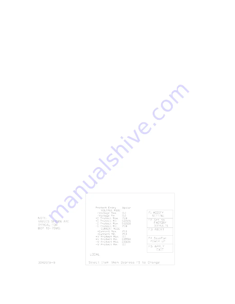
 to enter the Max/Min Settings submenu

(Figure 6). (If a Password is required, see Opera-
tor’s Manual for instructions.) 

3. Highlight the voltage or current max/min value

and press 

!

 to change it. Software limits are

absolute values (do not use minus sign for nega-
tive limits). Use number keys to change the set-
ting, then 

$

 to save. 

4. When complete, press 

$

 to save for power-up,

#

 to abort, or 

%

 to apply the changes (without

saving for power-up) and exit.

5. Upon return to the power-up screen, the main

channel (voltage or current) is compared against
the main channel limits in effect. If the main chan-
nel exceeds the limit, it is set to zero. 

6.  Highlight the ±CPROTECT or ±VPROTECT max/

min value and press 

!

 to change it. Software

limits are absolute values (do not use minus sign
for negative limits). Use number keys to change
the setting. Press 

$

 to save, or 

%

 to abort. 

7. When complete, press 

$

 to save for power-up,

or 

#

 to abort, or 

%

 to apply the changes (with-

out saving for power-up) and exit.

Upon return to the power-up screen, the new protec-
tion limit (voltage or current) is compared against the
protection limits in effect. If the new protection limit
setting is below the existing setting for the protection
limit, the protection channel (voltage or current) is
set to zero.

FIGURE 6.  MAX/MIN SETTING MENU

VOLTAGE

SOURCE

VOLTAGE

CURRENT

0.0000 0.0000

Содержание BOP 10-100MG

Страница 1: ...inted as a handy reference The BOP 1KW MG Operator s Manual also includes a full description of the digital interfaces and the SCPI command language FIRMWARE VERSION Refer to www kepcopower com suppor...

Страница 2: ...cell arrays and powering many electrochemi cal reactions II UNPACKING This instrument has been thoroughly inspected and tested prior to packing and is ready for operation After careful unpacking insp...

Страница 3: ...112113 228 1692 REV 3 3 KEPCO INC 131 38 SANFORD AVENUE FLUSHING NY 11355 U S A TEL 718 461 7000 FAX 718 767 1102 http www kepcopower com email hq kepcopower com FIGURE 1 BOP OUTPUT CHARACTERISTICS...

Страница 4: ...to DTE equipment and one with female pins to connect to a PC personal com puter two RS 232 Loop Back test Connectors one 6 pin and one 8 pin to test RS 232 communication and aid in isolating RS 232 co...

Страница 5: ...with a current rating compatible with the anticipated input current Line cords available as accessories are listed in Table 3 Plug the source power connector into the source power inlet connec tor at...

Страница 6: ...put for use with SCPI TRG and TRIG commands Refer to Operator s manual for details GPIB CONNECTIONS Your computer must have a GPIB interface card installed Connect the power supply to the computer s G...

Страница 7: ...port located on the rear panel See Fig ure 3 A Null Modem cable is not required for older MAC computers with D sub serial port in which the RXD and TXD line transposition is accomplished via external...

Страница 8: ...tem on the list and pressing the View Modify function key Menus and submenus will display a list of parameters with the top one high lighted The function key assignments can vary but generally offer t...

Страница 9: ...n1 Admin2 or Unprotected Series Parallel Configuration Standalone Parallel Series Master 2X2 Master 3X2 for parallel or series Unit Type Stand alone Master 1 to 4 Slave 1 to 5 and Connection Type show...

Страница 10: ...R CURRENT AND ASSOCIATED PROTECT LIMITS From the power up screen the settable voltage current parameters are displayed at the bottom of the LCD above the HELP message Use Y or U to highlight the main...

Страница 11: ...rmine the maximum value of voltage or current that can be programmed 1 Press from the power up screen to enter the General Setup menu then highlight Max Min Set tings 2 Press to enter the Max Min Sett...

Страница 12: ...nabled the pre existing settings for volt age current protect and voltage limit are restored WARNING For both inductive loads and con stant current type active electronic loads when the BOP output is...

Страница 13: ...F For con stant voltage type active electronic loads this mode stops energy flow during the OFF state Table 5 indi cates how the power supply responds to a command to go from Output ON to OFF CONFIGUR...

Страница 14: ...copower com email hq kepcopower com FIGURE 1 BOP 1KW OUTLINE DIMENSIONS SHEET 1 OF 2 20 000 508 00 21 439 544 54 22 800 579 11 21 564 547 73 22 000 558 79 23 863 606 12 18 235 463 16 18 985 482 21 1 4...

Страница 15: ...FLUSHING NY 11355 U S A TEL 718 461 7000 FAX 718 767 1102 http www kepcopower com email hq kepcopower com FIGURE 1 BOP 1KW OUTLINE DIMENSIONS SHEET 2 OF 2 SLIDES TRAVEL DISTANCE 23 000 584 2 22 000 5...

Страница 16: ...16 228 1692 REV 3 112113 KEPCO INC 131 38 SANFORD AVENUE FLUSHING NY 11355 U S A TEL 718 461 7000 FAX 718 767 1102 http www kepcopower com email hq kepcopower com...

Отзывы: