TK-2317
22
2-2. First Mixer
The signal from the front end is mixed with the fi rst local
oscillator signal generated in the PLL circuit by Q406 to pro-
duce a fi rst IF frequency of 49.95MHz.
The resulting signal passes through the XF401 MCF to
cut the adjacent spurious and provide the optimum charac-
teristics, such as adjacent frequency selectivity.
CIRCUIT DESCRIPTION /
电路说明
2-3. IF Amplifi er Circuit
The fi rst IF signal is passed through a four-pole mono-
lithic crystal fi lter (XF401) to remove the adjacent channel
signal. The fi ltered fi rst IF signal is amplifi ed by the fi rst IF
amplifier (Q405) and is then applied to the IF system IC
(IC401).
The IF system IC provides a second mixer, limiting
amplifier, quadrature detector and RSSI (Received Signal
Strength Indicator). The second mixer mixes the fi rst IF sig-
nal with the 50.4MHz signal of the second local oscillator
output (Q403) and produces the second IF signal of 450kHz.
The second IF signal is passed through the ceramic fi l-
ter (Wide: CF402, Narrow: CF401) to remove the adjacent
channel signal. The fi ltered second IF signal is amplifi ed by
the limiting amplifi er and demodulated by the quadrature de-
tector with the ceramic discriminator (CD401). The demodu-
lated signal is routed to the audio circuit.
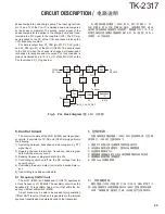
2-4. Wide/Narrow Switching Circuit
Wide and narrow settings can be made for each channel
by switching the ceramic fi lters CF401 (narrow).
The second IF signal always passes the ceramic fi lters
CF402 (Wide).
The wide and narrow switching data is output from the
MCU (IC820).
D401 and D402 are switched to ceramic fi lters when a
narrow mode is selected.
Q404 turns on/off with the Narrow and the IC401 detector
output level is changed to maintain a constant output level
during wide or narrow signals.
IC401
WID/NAR
D401
IFOUT
MXO
IFI
QU
A
D
AFOUT
C404
R406
C402
C414
R408
R411
R415
D402
CF401
CF402
C424
R423
R424
Q401
R426
50C
AFOUT
CD401
Q404
R409
IC402
+
-
R471
Fig. 3 Wide/Narrow switching circuit /
2-2. 第一混频器
前端的信号与 PLL 电路产生的第一本振信号在 Q406 混频,
生成 49.95MHz 频率的第一中频信号。
生成的信号通过晶体滤波器 (XF401)。
2-3. 中频放大电路
第一中频信号通过晶体滤波器 (X F401) 消除相邻信道的信
号。经滤波的第一中频信号被第一中频放大器 (Q405) 放大并
进入中频系统芯片 ( IC401)。中频系统芯片提供第二混频器、
限幅放大器、正交检测器和 RSSI( 接收信号强度指示器 )。
第二混频器将第一中频信号与 50.4M H z 的第二本振信号输
出 (Q403) 进行混频,并生成 450kHz 的第二中频信号。
第二中频信号通过陶瓷滤波器 ( 宽 :CF402、窄 :CF401) 继
续消除相邻信道的信号。经滤波的第二中频信号被限幅放大
器放大并被带有陶瓷鉴频器 ( C D401) 的正交检测器解调。经
解调的信号进入音频电路。
2-4. 宽 / 窄切换电路
通过切换陶瓷滤波器 C F402( 宽 )、C F401( 窄 ) 可以对每
一信道进行宽,窄
¬
设置。
第二中频信号通过陶瓷滤波器 CF402( 宽 )。
宽、窄控制信号从 IC820 输出。
选择宽 / 窄电平时,将 D401 和 D402 切换到陶瓷滤波器。
Q404 伴随着宽 / 窄数据而接通 / 断开,IC401 检测器输
出电平经常变化用来维持宽或窄信号过程中的恒定输出电平。
图 3 宽 / 窄切换电路


