KDC-X879
10
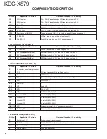
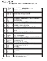
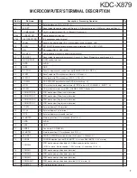
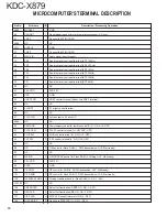
Pin No.
Pin Name
I/O
Description / Processing Operation
64,65
MODE0,1
-
GND
66
PAN RST
I
Reset signal request form system microprocessor (L : Reset)
67
VREF
-
Connect to 83PIN (VREF)
68,69
NC
-
NC
70,71
AVSS1,0
-
GND
72
VREF
-
Connect to 83PIN (VREF)
73
WAVE IN
I
Audio signal input terminal
74
F06
I
Spectrum analyzer input terminal (BPF 10KHz)
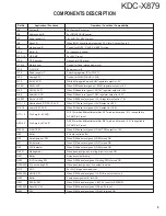
75
F05
I
Spectrum analyzer input terminal (BPF 3.3KHz)
76
F04
I
Spectrum analyzer input terminal (BPF 1KHz)
77
F03
I
Spectrum analyzer input terminal (BPF 330Hz)
78
F02
I
Spectrum analyzer input terminal (BPF 150Hz)
79
F01
I
Spectrum analyzer input terminal (BPF 63Hz)
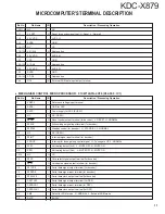
80
NC
-
NC
81
2.5V VDD
-
AVR 2.5V
82
VSS
-
GND
83
VREF CON
O
VREF control terminal (Connect to VREF terminal)
84
NC
-
NC
85
FLGCP3
O
FL bright control terminal
86
NC
-
NC
87
FL LATCH
O
Latch output to FL driver IC
88,89
NC
-
NC
90
REMO ON
O
Power supply control for remote control IC (H : ON, Hi-Z : OFF)
91
FL3.3V SW
O
FL3.3V control terminal (H : ON, Hi-Z : OFF)
92
FL+B SW
O
FL+B control terminal (H : ON, Hi-Z : OFF)
93
3.3V SW
O
3.3V control terminal (L : ON, Hi-Z : OFF)
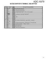
94
NC
-
NC
95
OE
O
OE control for Flash ROM (L : DATA transmission, Hi-Z : Wait ready)
96
NC
-
NC
97
WE/WR
O
WRITE/READ control for Flash ROM (L : Writing, Hi-Z : Wait ready)
98
3.3V VDD
-
AVR 3.3V
99
EVSS
-
GND
100
CE ROM
O
CE control for ROM (L : DATA transmission, Hi-Z : Wait ready)
101
CE F/ROM
O
CE control for Flash ROM (L : DATA transmission, Hi-Z : Wait ready)
102
FLASHROM CHECK
O
Writing condition check for Flash ROM (H : OK, L : NG)
103,104
NC
-
NC
105
GREEN LED
O
Select for illumination (GREEN H : ON, L : OFF)
106
RED LED
O
Select for illumination (RED H : ON, L : OFF)
107
DISP LED
O
DISP LED control (Normal H: ON, L : OFF)
108
BLACK DISP
O
Light up to DISP LED (H : ON, L : OFF)
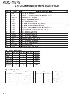
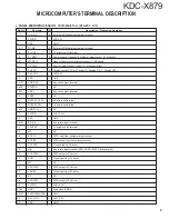
MICROCOMPUTER’S TERMINAL DESCRIPTION


