background image

English

  3

�����

��������������

���

�������������

���

�������������

��������

������

���
���

��

���

��

���

���

���

��

���

���

��

������

���

���

���

��� ����

��

���

���
��

���

���������

���������

������

��� ���������

��� ���������

�� ��

�� ��

��� ��

��� ��

��� ��

��

���

���

���

��

��

��

��� ���

���

�� ����

�� ��

��� ���

���

�� ����

���

���

���

��

��

����

���

����

����

��������������� ��� ��� ��������������� ��� ��
��������������� ��� ��� ��������������� ��� ��

��

��

��

��

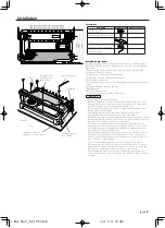
Installation board, etc.

(thickness : 15 mm or more)

Self-tapping screw

(ø5 × 18 mm)

Cooling fan

Installation

Accessories

Part name

External View Number of Items

Self-tapping screws 

(ø5 × 18 mm)

4

Hexagon socket head cap screw 

(M4 × 8 mm)

4

Cover 

1

Terminal cover (Power terminal)

1

Hexagon Wrench

1

Installation procedure

Since there are large variety of settings and connections possible according to 

applications, read the instruction manual well to select the proper setting and 

connection.

1. Remove the ignition key and disconnect the negative 

-

 terminal of the 

battery to prevent short circuits. 

2. Set the unit according to the intended usage.

3. Connect the input and output wires of the units.

4. Connect the speaker wires.

5. Connect the power wire, power control wire and grounding wire following this 

order.

6. Install the installation fittings in the unit.

7. Attach the unit.

8. Install the terminal cover.

9. Connect the negative 

-

 terminal of the battery.

2

CAUTION

•  Do not install in the below locations;

(Unstable location, In a location that interferes with driving, In a location 

that gets wet, In a dusty location, In a place that gets hot, In a place that 

gets direct sunlight, In a location that gets hit by hot air)

•  Do not install the unit under the carpet. Otherwise heat build-up occurs 

and the unit may be damaged.

•  Install this unit in a location which allows heat to easily dissipate.

Once installed, do not place any object on top of the unit.

•  The surface temperature of the amplifier will become hot during use. Install 

the amplifier in a place where people, resins, and other substances that are 

sensitive to heat will not come into contact with it.

•  This unit has cooling fans to decrease the internal temperature. Do not 

mount the unit in a place where the cooling fan and ducts of the unit are 

blocked. Blocking these openings will inhibit the cooling of the internal 

temperature and result in malfunction.

•  When making a hole under a seat, inside the trunk, or somewhere else in 

the vehicle, check that there is nothing hazardous on the opposite side 

such as a gasoline tank, brake pipe, or wiring harness, and be careful not to 

cause scratches or other damage.

•  Do not install near the dashboard, rear tray, or air bag safety parts.

•  The installation to the vehicle should securely fasten the unit to a place in 

which it will not obstruct driving. If the unit comes off due to a shock and 

hits a person or safety part, it may cause injury or an accident.

•  After installing the unit, check to make sure that electrical equipment 

such as the brake lamps, turn signal lamps and windshield wipers operate 

normally.

Hexagon socket 

head cap screw 

(M4 × 8 mm)

Hexagon Wrench

Cover 

Duct

Cooling fan

1.KAC-X621̲KE̲1US.indd

04.1.9, 11:45 AM

3

Содержание KAC-PS521

Страница 1: ...his instruction manual Familiarity with installation and operation procedures will help you obtain the best performance from your new power amplifier For your records Record the serial number found on the back of the unit in the spaces designated on the warranty card and in the space provided below Refer to the model and serial numbers whenever you call upon your KENWOOD dealer for information or ...

Страница 2: ...nd or cause the indicator letters to peel off To prevent battery rise When the unit is used in the ACC ON position without turning the engine ON it depletes the battery Use it after starting the engine Protection function There is a Protection function installed in the unit to protect the unit and speakers from various problems When Protection operates the display informs you of the condition Disp...

Страница 3: ...ise heat build up occurs and the unit may be damaged Install this unit in a location which allows heat to easily dissipate Once installed do not place any object on top of the unit The surface temperature of the amplifier will become hot during use Install the amplifier in a place where people resins and other substances that are sensitive to heat will not come into contact with it This unit has c...

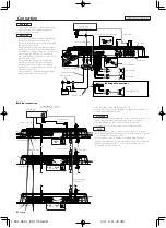
Страница 4: ... to appropriate speaker connectors separately Sharing the negative wire of the speaker or grounding speaker wires to the metal body of the car can cause this unit to fail After installation check that the brake lamps winkers and wipers work properly RCA cable Slave amplifier 7 Extension wire Set the ID number of the Master amplifier to 0 You can connect up to 7 Slave amplifiers Assign them ID numb...

Страница 5: ...l LINE OUT terminal The signal that s input from the line input terminal is output Power indicator Lights when the POWER switch is turned On The indicator flashes several seconds when the POWER switch is turned On or when the Protection function is activated LPF FREQUENCY control Sets the cutoff frequency when the FILTER switch is set to LPF HPF FREQUENCY control Sets the cutoff frequency when the...

Страница 6: ...10 12 15 17 kHz Treble Center Frequency TR G T 15 T 15 dB Treble level VOL 20 0 dB Volume offset TEMP FAHR Fahrenheit or CELS Centigrade The Fahrenheit or Centigrade temperature unit can be selected for the Display mode DEFA For the operation method refer to Default AMP 0 7 The ID Number you have assigned is displayed 4 Exit Menu mode Press the MENU button for at least 1 second NOTE When you hold ...

Страница 7: ... 100 200 Hz Bass Center Frequency BAS G BASS GAIN 15 15 dB Bass level Q FA Q FACTOR Q1 00 Q1 25 Q1 50 Q2 00 Bass Q Factor EXT BASS EXT ON OFF When the bass extend is set to ON low frequency response is extended by 20 TRE F TREB FREQ 10 12 15 17 kHz Treble Center Frequency TRE G TREB GAIN 15 15 dB Treble level VOL VOL OFFSET 20 0 dB Volume offset AMP NO AMP CONTROL NO 0 7 Select an ID number of the...

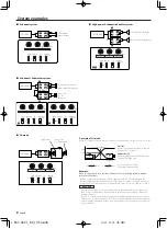
Страница 8: ... above The capacitor rating should be as close as possible to 331 25 µF and the coil rating should be as close as possible to 5 3 mH 2CAUTION If you wish to bridge connect a speaker the speaker impedance must be no less than 4 ohms Connecting a speaker with an impedance lower than 4 ohms may damage the unit Be sure to connect capacitors to speakers to which high frequencies will be passed Failure ...

Страница 9: ...Ω 2ch 1 0 THD N 179 W 165 W Normal 2 Ω 2ch 1 0 THD N 305 W 254 W 1 kHz Bridged 4 Ω 1 0 THD N 612 W 505 W 1 Dynamic Power B 14 4 V CEA 2006 191 W 170 W Output Regulation B 14 4 V CEA 2006 under 0 3 dB 4 Ω under 0 3 dB 4 Ω Signal to Noise Ratio CEA 2006 83 dBA W 4 Ω 81 dBA W 4 Ω Signal to Noise Ratio Bypass CEA 2006 83 dBA W 4 Ω 82 dBA W 4 Ω Sensitivity rated output MAX 0 2 V 0 2 V Sensitivity rated...

Страница 10: ...erie Il est préférable de l utiliser après avoir allumé le moteur Fonction de protection Une fonction de protection est installée dans l unité afin de protéger l unité et les enceintes de divers problèmes Lorsque la protection fonctionne l affichage vous informe de l état Affichage Information E 01 Lorsque l intérieur de l unité est en surchauffe E 02 Lorsque l unité est en panne et que l intensit...

Страница 11: ... que la chaleur puisse se dissiper aisément Après l installation ne placer aucum objet sur l appareil La surface de l amplificateur va chauffer pendant l utilisation Installer l amplificateur à un endroit où des passagers de la résine ou d autres substances sensibles à la chaleur n entreront pas en contact avec lui Cet appareil est pourvu de ventilateurs de façon à évacuer une partie de la chaleur...

Страница 12: ...e haut parleur appropriés La mise en commun du câble négatif d un haut parleur ou des fils de masse des haut parleurs à la carrosserie métallique de la voiture pourrait rendre l appareil inopérant Après l installation vérifier que les voyants de frein les clignotants et les essuie glace fonctionnent correctement Câble RCA Amplificateur esclave 7 Câble de rallonge Régler le numéro d identification ...

Страница 13: ... entrée de ligne constitue la sortie Voyant d alimentation S allume lorsque le commutateur POWER est mis en marche Le voyant clignote pendant plusieurs secondes lorsque le commutateur POWER est mis en marche ou lorsque la fonction de protection est activée Commande LPF FREQUENCY Cette commande permet de préciser la fréquence de coupure quand le commutateur FILTER est sur la position LPF Commande H...

Страница 14: ...gus VOL 20 0 dB Décalage de volume TEMP FAHR Fahrenheit ou CELS Centigrade L unité de température Fahrenheit ou Centigrade peut être sélectionnée pour le mode d affichage DEFA Pour la méthode de fonctionnement référez vous à Par défaut AMP 0 7 Le numéro d identification que vous avez attribué s affiche 4 Sortez du mode menu Appuyez sur la touche MENU pendant au moins 1 seconde REMARQUE Lorsque vou...

Страница 15: ... F BASS FREQ 60 80 100 200 Hz Fréquence centrale de basse BAS G BASS GAIN 15 15 dB Niveau de basses Q FA Q FACTOR Q1 00 Q1 25 Q1 50 Q2 00 Facteur d amplification dynamique Q EXT BASS EXT ON OFF Lorsque l expansion de basses est activée la réponse en basse fréquence est augmentée de 20 TRE F TREB FREQ 10 0 12 5 15 0 17 5 kHz Fréquence centrale d aigus TRE G TREB GAIN 15 15 dB Niveau d aigus VOL VOL...

Страница 16: ...ce cas la condensateur doit avoir une capacité aussi proche que possible de 331 25 µF et le bobine une capacité aussi proche que possible de 5 3 mH 2ATTENTION Si l on désire connecter en pont un haut parleur l impédance du haut parleur ne devra pas être inférieure à 4 ohms Le branchement d un haut parleur dont l impédance est inférieure à 4 Ohms peut endommager l appareil S assurer de connecter de...

Страница 17: ...ications Les spécifications sont sujettes à modifications sans préavis Section audio KAC X621 KAC X521 Sortie de puissance RMS B 14 4 V CEA 2006 Normal 4 Ω 2can 1 0 THD N 179 W 165 W Normal 2 Ω 2can 1 0 THD N 305 W 254 W 1 kHz En pont 4 Ω 1 0 THD N 612 W 505 W 1 Puissance dynamique B 14 4 V CEA 2006 191 W 170 W Régulation de tension B 14 4 V CEA 2006 inférieur à 0 3 dB 4 Ω inférieur à 0 3 dB 4 Ω R...

Страница 18: ...otor Función de protección La unidad tiene instalada una función de protección con el fin de proteger a la unidad y a los altavoces de algunos problemas Cuando dicha protección funciona la pantalla informa sobre esta condición Visualización Información E 01 Cuando el interior de la unidad se recalienta E 02 Cuando la unidad ha fallado y se genera tensión de corriente directa hacia la salida del al...

Страница 19: ... contrario éste podría sobrecalentarse y estropearse Instale este aparato en un lugar donde el calor pueda disiparse fácilmente Una vez instalado no ponga nada sobre él La temperatura de la superficie del amplificador se elevará durante su uso Instale el amplificador en un lugar seguro donde personas resinas y otras substancias sensibles al calor no entren en contacto con esta superficie Esta unid...

Страница 20: ...ocircuitos Conecte los cables del altavoz a los conectores adecuados del altavoz separadamente La puesta en contacto de terminales de altavoces distintos o la conexión como toma de tierra de los terminales del altavoz al coche del automóvil pueden causar daños a la unidad Después de la instalación compruebe que las lámparas del freno luces de destello y limpiaparabrisas funcionar correctamente Cab...

Страница 21: ...linea LINE OUT La señal de entrada del terminal de entrada de línea es la salida Indicador de alimentación Se ilumina cuando se activa el interruptor POWER El indicador parpadea durante varios segundos cuando se activa el interruptor POWER o cuando se activa la función de protección Control LPF FREQUENCY Ajusta la frecuencia de corte cuando el conmutador FILTER está en LPF Control HPF FREQUENCY Aj...

Страница 22: ... TREB 10 12 15 17 kHz Frecuencia central de agudos TR G T 15 T 15 dB Nivel de agudos VOL 20 0 dB Compensación de volumen TEMP FAHR fahrenheit o CELS centígrados Es posible seleccionar para el modo de visualización la temperatura en grados fahrenheit o centígrados DEFA Para el método de funcionamiento remítase a Ajustes de fábrica AMP 0 7 El número ID que ha asignado se visualiza 4 Salir del modo d...

Страница 23: ...SLOW o OFF BAS F BASS FREQ 60 80 100 200 Hz Frecuencia central de graves BAS G BASS GAIN 15 15 dB Nivel de graves Q FA Q FACTOR Q1 00 Q1 25 Q1 50 Q2 00 actor Q de graves EXT BASS EXT ON OFF Cuando la extensión de graves se activa la respuesta de baja frecuencia se extiende en un 20 TRE F TREB FREQ 10 0 12 5 15 0 17 5 kHz Frecuencia central de agudos TRE G TREB GAIN 15 15 dB Nivel de agudos VOL VOL...

Страница 24: ...ales del capacitor deberán ser lo más parecido posible a 331 25 µF y las especificaciones nominales de la bobina deverán ser lo más parecido posible a 5 3 mH 2PRECAUCIÓN Si se desea conectar en puente un altavoz la impedancia del altavoz no debe ser inferior a 4 ohmios Conectar un altavoz con una impedancia inferior a 4 ohmios pueden estropear el aparato Asegúrese de conectar los capacitores a los...

Страница 25: ...l 4 Ω 2ch 1 0 THD N 179 W 165 W Normal 2 Ω 2ch 1 0 THD N 305 W 254 W 1 kHz Puenteada 4 Ω 1 0 THD N 612 W 505 W 1 Potencia dinámica B 14 4 V CEA 2006 191 W 170 W Regulación de salida B 14 4 V CEA 2006 bajo 0 3 dB 4 Ω bajo 0 3 dB 4 Ω Relación señal a ruido CEA 2006 83 dBA W 4 Ω 81 dBA W 4 Ω Relación señal a ruido desvío CEA 2006 83 dBA W 4 Ω 82 dBA W 4 Ω Sensibilidad salida nominal MAX 0 2 V 0 2 V S...

Страница 26: ...1 KAC X621 KE 3Spanish indd 04 1 9 11 47 AM 26 ...

Страница 27: ...1 KAC X621 KE 3Spanish indd 04 1 9 11 47 AM 27 ...

Страница 28: ...1 KAC X621 KE 3Spanish indd 04 1 9 11 47 AM 28 ...

Отзывы: