


©
www.kemper-olpe.de
– 05.2019 / K410068602012-00 – 25 / 32
1
Installation
1.1
2
Electrical connection of the KHS Timer
2.1
Overview of the board | Terminal description
KHS Timer
The leak controller is intended for wall instal-
lation. The housing has 4 each ø 4 mm moun-
ting holes in a clearance of w = 148 mm and
h = 50 mm.
To mount the cover, open the device and
screw tightly to the wall. After mounting the
housing, make the required electrical connec-
tions.
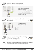
Connection power supply
Connection Free Drain float switch
overflow monitoring
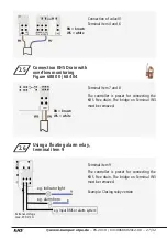
Connections alarm relay
1.2
KHS quarter turn stop
valves
See separate installation and operating in-
structions, Figure 686 04 or Figure 686 05.
Connection valve
}
}
}