background image

14

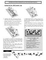
Laying the fire 

– 700 Ceramic Log

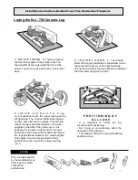
2. LOCATE L O G  N O. 1 :  This is the largest log that

is positioned at the rear of the grate.Two locating pins

are positioned at the rear of the burner. The large
log has two holes on the underside to position in
place

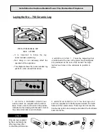
1 . L O C AT E  4  C E R A M I C COALS:  Four 
ceramic coals are  supplied with the burner 
base. These coals must be laid in the position 
indicated on the drawing with the taller coals on 
the ends and smaller coals in-between.

3 . LOC ATE  LOG 

NO’S  2  &  3:  Two front log no’s. 2

and 3 are supplied to fit into the space between the metal 
frame and the ceramic base. These logs do not cover the 
front burner ports but are designed to deflect the front flame 
back into the fire.

L O G S

P O S I T I O N I N G   OF 

A L L  L O G S

•  It    is    important    to    follow    the    log 

recommended  positioning.

•  Not   doing  so  can  adversely  effect  the 

operation of the appliance.

•  This diagram shows the recommended log 

positions, when viewed from above.

Only use logs supplied 
by the manufacturer as 
other logs may effect 
combustion performance

Installation Instructions Kemlan Power Flue Horizon Gas Fireplaces

Содержание Power Flue Horizon Gas Fireplaces

Страница 1: ... FIREPLACES Installation Instructions Power Flue Horizon Gas Fireplaces ...

Страница 2: ... SEE NEXT PAGE FOR LOCATION EQUIREMENTS Model Type 2 Power Flue Decorative Gas Fireplace DATA PLATE Refer to data plate for information in respect to gas pressure consumption and gas type Natural or LPG Data Plate is located under the gas burner and is accessed by lifting front access panel or removing base plate 700 Low Line 700 Mk2 Pebble 700 Mk2 Coal 700 Ironbark Log Mk4 850 Low Line 800 Mk2 Pe...

Страница 3: ...Appliances over 150 MJ h input From a mechanical air inlet including a spa blower MIN CLEARANCE mm 300 500 300 500 1000 500 150 g 500 500 h j 50 150 150 k n Vertically below an openable window non mechanical air inlet or any other opening into a building with the exception of sub floor ventilation See table below NOTES I All distances are measured vertically or horizontally along the wall to a poi...

Страница 4: ...lue draws well with smoke pellet Kemlan recommends that all gas fires be serviced every year All gas units must be fitted by a licensed gas fitter It is the responsibility of the gas fitter to follow the regulations set out in the Gas Code that dictate the procedures to follow when installing a gas appliance particularly regarding gas pipe sizing and checking of pressures Installation 1 The N D E ...

Страница 5: ...05 770 1095 1210 225 10 15 1100 LOW LINE 1100 275 405 770 1345 1210 225 10 15 1500 LOW LINE 1500 290 435 900 1746 1210 250 10 15 2000 LOW LINE 2000 290 435 900 2246 1210 250 10 15 LIP FRAME DETAIL TYP SINGLE SIDED A A1 B B1 C D D1 E F G CANTLEVER 700 1190 1266 440 478 455 228 1010 177 405 336 CANTLEVER 1100 1420 1500 440 478 455 228 1010 177 405 336 CANTLEVER 1500 1850 1935 440 478 455 254 1010 17...

Страница 6: ... TRANSFER BOX SILENCER 8 x 900 REDUCER 7 6 8 6 9 6 10 6 12 6 14 6 GAS COWL COOLING ROTOR INBUILT THERMAL OVERLOAD COOLING IMPELLER 6 x 900 12 x 900 Installation Instructions Kemlan Power Flue Horizon Gas Fireplaces 12 x 200 VENTED FLUE ...

Страница 7: ...x 900 REDUCER 7 6 8 6 9 6 10 6 12 6 14 6 WALL MOUNTED FAN 2x 8 45 DEG 12 8 REDUCING CAP 6 x 900 12 x 900 Installation Instructions Kemlan Power Flue Horizon Gas Fireplaces 2x 6 45 DEG 12 x 200 VENTED FLUE 10MM GAP BETWEEN END OF FLUE TO WALL ...
Страница 8: ...PLASTERBOARD C INTERNAL FRAME HEIGHT WHEN USING HEAT ZONE KIT REFER TO HEAT ZONE CONVERSION PAGE SINGLE SIDED A B B C C 700 LOW LINE 1056 410 420 750 1050 850 LOW LINE 1145 450 460 845 1145 1100 LOW LINE 1408 450 460 845 1145 1500 LOW LINE 1796 480 490 950 1280 2000 LOW LINE 2293 480 490 950 1280 INCLUDING 10mm PLASTERBOARD C INTERNAL FRAME HEIGHT WHEN USING HEAT ZONE KIT REFER TO HEAT ZONE CONVER...

Страница 9: ...ELECTRICAL SWITCH 240 V PLUG INTERNAL FAN SIDE EXIT EXTERNAL FAN SIDE EXIT FRAMEWORK AND 10MM WALL LINING BY INSTALLER 150MM MIN Installation Instructions Kemlan Power Flue Horizon Gas Fireplaces MUFFLER 25MM CLEARANCE TO TIMBER 300MM CLEARANCE TO EAVES 75MM MIN CLEARANCE TO TIMBER INTERNAL FAN CASING ACCESS PANEL FOR FAN SERVICE TO ARCHITECTS DETAIL 400 x 400MM MIN 75MM MIN CLEARANCE TO TIMBER MU...

Страница 10: ... by turning off wall switch System does not have a high low burner switch Laying the fire Coal Pebble Evenly spread a bag of Vermiculite into the burner tray Tray should be completely filled to the top with Vermiculite to a depth of approximately 45mm Unpack the coals pebbles contained in a clear plastic bag and lay a row of coals pebbles on the vermiculite along the back of the burner tray leavin...

Страница 11: ...2 PEBBLES 1000 992 X 135 MARK 2 COALS 1400 1400 X 64 MARK 2 PEBBLES 1400 1400 X 64 MARK 2 COALS 1800 1800 X 64 MARK 2 PEBBLES 1800 1800 X 64 MARK 2 COALS 1000 992 X 135 MARK 2 PEBBLES 700 800 600 X 155 Installation Instructions Kemlan Power Flue Horizon Gas Fireplaces ...

Страница 12: ...r The large log has two holes on the underside to position in place 1 L O C AT E 4 C E R A M I C C OA L S Four ceramic coals are supplied with the burner base These coals must be laid in the position indicated on the drawing with the taller coals on the ends and smaller coals in between 3 LOCATE LOG NO S 2 3 Two front log NO S 2 3 are supplied to fit into the space between the metal frame and the ...

Страница 13: ... on the right hand side of the burner on the rear log in front of the pilot Charred end facing inwards The left hand side of the log is positioned between the metal uprights on the side of the grate LOCATE LOG NO 7 The charred effect of the log is positioned on the smaller coal in the centre of the burner on the right hand side LOCATE LOG NO 8 This smaller log is placed on the top of log NO 2 and ...

Страница 14: ...n between 3 LOCATE LOG NO S 2 3 Two front log no s 2 and 3 are supplied to fit into the space between the metal frame and the ceramic base These logs do not cover the front burner ports but are designed to deflect the front flame back into the fire L O G S P O S I T I O N I N G OF A L L L O G S It is important to follow the log recommended positioning Not doing so can adversely effect the operatio...

Страница 15: ...the right hand side of the burner with the right hand side of the logs positioned between the metal uprights of the grate Two pins are provided to firmly position these two logs onto the large rear log no 1 P O S I T I O N I N G O F A L L L O G S It is important to follow the log recommended positioning Not doing so can adversely effect the operation of the appliance This diagram shows the recomme...

Страница 16: ...NOT spray aerosols in the vicinity of this appliance whilst it is in operation DO NOT modify this appliance Primarily a decorative appliance not certified as a space heater 6 The appliance is a live fuel effect product designed to operate with luminous flames and may exhibit slight carbon deposition 7 The guard is fitted to this appliance to reduce the risk of fire or injury from burns and no part...

Страница 17: ...Diagram For further service information contact Kemlan Australia Installation Instructions Kemlan Power Flue Horizon Gas Fireplaces Head Office 13 French Avenue Brendale Queensland 4500 Telephone PH 07 3490 5500 ...

Страница 18: ...CTIONS CHECK FAN ON INDEPENDENT POWER SWITCH FAN COMES ON PILOT ON MAIN BURNER DOES NOT LIGHT 1 FLAME SENSOR NOT SENDING SIGNAL TO OPEN VALVE CHECK ELECTRODE IS IN PILOT FLAME CLEAN ELECTRODE CHECK ELECTRODE CONNECTIONS REPLACE ELECTRODE IF DAMAGED 2 MODULE NOT SENDING CHECK CONNECTIONS SIGNAL TO OPEN VALVE REPLACE MODULE 3 FAULTY VALVE REPLACE VALVE FLAME FAIL LOCKOUT UNIT HAS DETECTED LOSS OF FL...

Страница 19: ...DING SIGNAL TO OPEN VALVE FLAME CHECK ELECTRODE CONNETCTIONS CLEAN ELECTRODE CHECK ELECTRODE FOR DAMAGE REPLACE ELECRODE 2 MODULE NOT SENDING REPLACE MODULE SIGNAL TO OPEN VALVE 3 FAULTY VALVE REPLACE VALVE FLAME FAIL LOCKOUT 1 POWER FAILURE TURN ON OFF SWITCH OFF AND UNIT HAS DETECTED LOSS OF FLAME AND LOCKED OUT ON AGAIN TO RESET ONCE POWER ESTABLISHED 2 GAS SUPPLY CHECK GAS PRESSURE AND ADJUST ...

Страница 20: ...n box If a fault occurs the sequence of the flashing red light indicates the fault These codes are listed below The green light indicated the ignition box is sensing the flame Fan Forced Models The codes above still apply plus the codes below Atmospheric Models Flash Code Meaning Possible Cause Red LED Long 1 short 0 Running OK Appliance running correctly Green LED will be on 2 1 Maximum retries e...

Страница 21: ...fore carrying out repairs turn off the power visually inspect all cables and connections for damage or corrosion On start up once the unit has passed the self test and pressure switch is closed on fan forced models you should be able to hear a clunk from the gas valve as it opens If no sound from the gas valve check connections If the valve clunks but no ignition check gas supply and spark electro...

Страница 22: ...rive or microcontrollers disagree 2 4 Hardware failure on GAS1 valve drive or microcontrollers disagree 2 5 Hardware failure on GAS2 valve drive or microcontrollers disagree 2 6 Hardware failure on flame sensor 2 7 Relay Enable signal hardware failure stuck in ON state 3 1 Lockout due to pressure switch opening 3 2 Lockout due to EE memory corruption 3 3 Lockout due to inter microcontroller commun...

Отзывы: