


35
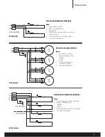
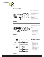
Coil heathers
Time/Pressure termination system
All cooler units Reverse cycle/hot gas defrost
Pressure equivalent to 25°C SST of the system refrigerant
Defrost Termination
If a defrost termination thermostat is to be fitted then the normal starting position of the defrost probe is 1/3rd of the way
along the coil face (air on) and about 2/3rds up away from any heater elements. Once the system is in operation it may be
necessary to relocate the probe to the area of the coil where ice remains the longest during defrost (possibly air off face).
16. COIL HEATERS
Coil block heaters are either ‘U’ bent or straight and they have to be disconnected from the terminal box at the electrical con-
nection end and sometimes from the auxiliary terminal box at the refrigeration connection end of the cooler. These heaters
are withdrawn and replaced from the refrigeration connection end of the cooler taking care to retain the ‘anti-creep’clips.
These clips may be re-used but will possibly need retensioning. To avoid damage to either the coil fins or the heater cable,
the heater cable should be inserted into a similar length of 1/4” OD copper tube and fed carefully through the fins with a twist-
ing motion. With care the heater element sheaths can be curved through 90° (minimum radius 600mm) for removal and refit-
ting purposes. Before attempting to refit a heater it is essential to ensure that the coil heater hole has not become obstructed
with ice and wherever possible the coil block should be above freezing point.
Drain Pan Heaters
Replacement is achieved by disconnecting the elements from the terminal box(es) after removing the end cover and drain
pan, and unclipping/unscrewing the heater retaining clips.
17. INITIAL STARTING
Before running the unit for the first time, check that all guards, motor mountings and electrical covers are secure, all
unnecessary terminal block links are removed and fans rotate freely. Remove any lifting channels.
•
Check that that the unit is secured in the correct manner specified in section 6. Only fix the unit using the mounting slots
provided.
•
Check that the fan rotation of 3 phase units is correct. Reversing any two phases of the motor supply will change the
rotation (AC fan sets only).


