©2014 4Front Engineered Solutions, Inc.
10
6004753N — Hydraulic Dock Leveler - One Button Control — Safe
T
Frame
™
March 2014
Cylinder
mounting pad
3/4"
anchor
bolt
(supplied
by others)
Stagger and weld
6" x 12" shims
insTaLLaTion,
continued
11. If a field installed riser kit is being used, do not use
hydraulics to position leveler on maintenance strut before
cylinder support riser is in place. Use a suitable lifting
device to place leveler on maintenance strut per step
12 below, then position and weld in the cylinder support
bracket. If electrical power is available, reconnect power
and use the electrical controls to raise the ramp and lip to
their full above dock position. See operating instructions
on front cover of control box. If electrical power in not
available, raise ramp using a chain or other suitable
lifting device.
Hydraulic pressure or mechanical support must be
maintained on the ramp and lip to hold them in the raised
position until the maintenance strut and lip lock are in
place. DO NOT WORK UNDER THE DOCK LEVELER
RAMP OR LIP UNLESS THE MAINTENANCE STRUT IS IN
PLACE AND PINNED, AND LIP LOCK IS IN PLACE AND
SUPPORTING THE LIP.
12. Return power to the leveler control. Using the push-
button control station or a suitable lifting device, two
people are required to perform the following steps to
secure the leveler with the maintenance strut and lip
lock.
a. One person must push and hold the
raise
button
until dock leveler reaches its highest position, lip
extends fully and hold dock leveler and lip in their
highest position.
b. The second person positions the maintenance strut
into the bracket located on the underside of the ramp
assembly and pins it in place with hairpin clip. See
Fig. 15 and the instruction label on maintenance
strut.
c. The second person then locks the lip in extended
position with the lip lock provided under the deck.
Pull the lip lock outward as far as it will go. Release
lip lock. See instruction label on dock leveler beam
near lip lock.
d. Release button control and allow leveler to lock in
maintenance position.
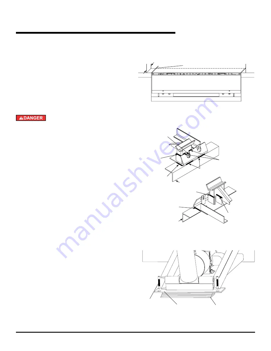
13. 6x16" shims of the proper thickness are to be placed
under the ramp cylinder mounting pad and welded out
as shown in Fig. 13.
Fig. 12
Flush with floor at this point
Door jamb
Fig. 11
Fig. 13
1/2" sq. drive
adjustment bolt
CCW rotation
to raise
3/16" weld
(both sides)
3/16" weld
3" long (min.)
(both sides)
3/16" weld
(both sides)
3/16" weld
3" long (min.)
(both sides)
3/16" weld
3" long (min.)
3/16" weld
3" long (min.)
3/16" weld
Curb steel
Curb steel


