background image

Quick Start Guide

Integra Series  11

Start-up software 

Models 2700, 2701, and 2750

 – You can use the “Up & Running with TestPoint” 

software (supplied on CD) to perform the following:

Control and configure the Integra instrument

Scan, acquire, and graph the data

Store data on disk for analysis

Save and recall instrument scan configurations

Model 2701

 – A built-in web page is available to allow for easy Ethernet communi-

cation between the instrument and the computer. From this web page, you can 
read and set network parameters and other data stored in the Model 2701. It also 
takes readings and allows you to send command strings and receive data.

Using Internet Explorer (IE 5.0 or greater), a local intranet address is used to open 
the web page. The web page address is the same as the IP Address of the Model 
2701. Assuming the default IP Address is being used, the following intranet 
address will open the web page:  

http://192.168.0.2

NOTE

Details on using the Ethernet web page with the Model 2701 is pro-
vided in Section 10 (see “Internal web page”) of the Model 2701 
User’s Manual. 

Trigger and return readings

Remote programming

 – The following SCPI command sequence is used to trig-

ger a finite number of measurements and return the readings. It is assumed that 

Factory defaults

 have been previously restored. 

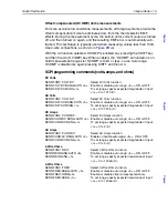
INIT:CONT OFF

‘ Disables continuous measurements. Measurements will not
‘ be performed until the instrument is triggered.

TRIG:COUN <n>

‘ Sets the trigger count: <n> = 1 to 9999. This specifies the
‘ number of measurements to be performed.

READ?

‘ Triggers measurement(s) and requests reading(s).

Included with each returned reading is a timestamp and a reading number (Read-
ing, Timestamp, Reading Number). For example:

1.0001VDC, +8694.16SECS, +6141RDNG#

The 10VDC reading is returned in exponent format. When the Model 27xx was 
turned on, the timestamp and reading number started at zero. For the above 
example, the measurement occurred 8,694.16 seconds after the unit was turned 
on, and the reading was the 6,141

st

 taken since the unit was turned on.

To
p

ic

s

To
p

ic

s

To
p

ic

s

Содержание Integra 27 Series

Страница 1: ...Model 27XXIntegra Series Quick Start Guide A G R E A T E R M E A S U R E O F C O N F I D E N C E...

Страница 2: ...CT INDIRECT SPECIAL INCIDENTAL OR CONSEQUENTIAL DAMAGES ARISING OUT OF THE USE OF ITS INSTRUMENTS AND SOFTWARE EVEN IF KEITHLEY INSTRUMENTS INC HAS BEEN ADVISED IN ADVANCE OF THE POSSIBILITY OF SUCH D...

Страница 3: ......

Страница 4: ...Model 27XX Integra Series Quick Start Guide 2003 Keithley Instruments Inc All rights reserved Cleveland Ohio U S A First Printing May 2003 Document Number 27XX 903 01 Rev A...

Страница 5: ...uld incorporate immediately into the manual Addenda are numbered sequentially When a new Revision is created all Addenda associated with the previous Revi sion of the manual are incorporated into the...

Страница 6: ...cted to mains voltage or to voltage sources with high transient over voltages Measurement Category II connections require protection for high transient over voltages often as sociated with local AC ma...

Страница 7: ...oltages The symbol indicates a connection terminal to the equipment frame The WARNING heading in a manual explains dangers that might result in personal injury or death Always read the associated info...

Страница 8: ...QuickStartGuide Integra Series...

Страница 9: ...page 31 Storing readings page 31 Front panel input connections page 12 Recalling readings and statistics page 31 Basic measurements page 14 Model 7700 switching module page 34 Measure volts amps and...

Страница 10: ...on topics covered in the guide and full details on topics not covered in this guide Details on the Model 7700 switching module is covered in the Model 27xx User s Manual Details on Model 7700 install...

Страница 11: ...surements any of these 20 2 pole input channels can be connected via relay switches to the DMM of the mainframe For 4 wire measurements e g 4 the channels are paired Input channels 1 through 10 are pa...

Страница 12: ...OFF DELAY HOLD SAVE SETUP CONFIG HALT TYPE LSYNC TEST MONITOR STEP SCAN OCOMP CH OFF CARD CLOSE Integra Series RS 232 GPIB For RS 232 communication connect to serial port of computer using a straight...

Страница 13: ...PUT RATIO ACV ACI 2 4 FREQ TEMP CH AVG CONT PERIOD SENSOR LIMITS ON OFF DELAY HOLD SAVE SETUP CONFIG HALT TYPE LSYNC TEST MONITOR STEP SCAN OCOMP CH OFF CARD CLOSE INTEGRA SERIES RS 232 ETHERNET CAT I...

Страница 14: ...or GPIB communication connect to GPIB port of computer using an IEEE 488 cable Keithley 7007 Communications configuration GPIB Press SHIFT and then EXIT GPIB to access menu Use the edit keys to enable...

Страница 15: ...wer cord Failure to use a grounded outlet may result in personal injury or death due to electric shock 4 Turn on the instrument by pressing the front panel power switch to the on I position After goin...

Страница 16: ...s Manual Detailed information on the Ethernet interface is provided in the Model 2701 User s Manual and the Model 2701 Instrument Networking Instruction Manual For remote programming the following in...

Страница 17: ...th the following settings IP Address 192 168 000 002 Subnet Mask 255 255 255 000 Gateway 192 168 000 001 The interface settings for your computer must be compatible with the interface set tings for th...

Страница 18: ...NOTE Details on using the Ethernet web page with the Model 2701 is pro vided in Section 10 see Internal web page of the Model 2701 User s Manual Trigger and return readings Remote programming The fol...

Страница 19: ...LO terminals 4 wire measurements The 4 wire connections to front panel inputs are shown in Figure 6B Use these connections for 4 and TEMP 4 wire RTD measure ments Maximum inputs front panel The maximu...

Страница 20: ...MPS HI INPUT LO SENSE W 4 WIRE INPUTS 350V PEAK 1000V PEAK R F F F 500V PEAK FRONT REAR 3A 250V AMPS HI INPUT LO SENSE W 4 WIRE INPUTS 350V PEAK 1000V PEAK R F F F 500V PEAK FRONT REAR 3A 250V AMPS HI...

Страница 21: ...6B for 4 wire ohms a connections 2 Function As shown in Figure 7 press the DCV ACV DCI ACI 2 or 4 key to select the measurement function 3 Range As shown in Figure 7 enable auto range or manually sel...

Страница 22: ...LT DC RANG n To set range specify expected magnitude of input n 0 to 1010 V AC Volts SENS FUNC VOLT AC Select AC Volts function SENS VOLT AC RANG AUTO b Enable or disable auto range b ON or OFF SENS V...

Страница 23: ...o be connected directly to the input terminals of the module Input connections and measurements for the Model 7700 are covered on page 35 Step 3 of the following procedure explains how to select and c...

Страница 24: ...ctly connected to a Keithley switching module that has a cold junction for thermocouples such as the Keithley 7707 switching module Details on the Model 7700 switch ing module are provided on page 34...

Страница 25: ...the SHIFT key then press FREQ PERIOD 3 Select a measure range that will accommodate the expected AC input level 4 Reading Take a reading from the display SCPI programming commands frequency and period...

Страница 26: ...below the set threshold pass con dition the unit will beep and display the resistance reading If the tested circuit is above the threshold fail condition the message OPEN will be displayed SCPI progra...

Страница 27: ...ion is displayed For front panel operation the selected display resolution is the same for all functions Filter Press to enable or disable Type Press SHIFT then FILTER TYPE to access filter configurat...

Страница 28: ...rol Measurement speed rate For the volts amps ohms and temperature measurements the RATE key sets the integration time measurement speed of the A D converter The integration time is the period of time...

Страница 29: ...d amps BANDwidth commands can be used to set measurement bandwidth see Model 27xx User s Manual for details Remote programming example nplc SENS VOLT DC NPLC 2 Sets rate for DC Amps to 2 PLC NOTE When...

Страница 30: ...or REPEAT SCPI programming commands filter For remote programming AVER commands are used to configure and control enable disable the digital filter Each valid function can have its own unique filter c...

Страница 31: ...Set filter count to 10 SENS RES AVER TCON REP Select Repeat filter type SENS RES AVER STAT ON Enable filter NOTE When finished with remote programming press the LOCAL key to restore front panel contro...

Страница 32: ...R STAT OFF Disable autozero NOTE When finished with remote programming press the LOCAL key to restore front panel control Math operations The following math operations can be performed on an input sig...

Страница 33: ...re readings will be the actual input minus 1V SCPI programming commands relative DC Volts SENS VOLT DC REF n Specify rel value n 1010 to 1010 V SENS VOLT DC REF STAT b Enable or disable rel b ON or OF...

Страница 34: ...REF STAT ON Enables rel NOTE When finished with remote programming press the LOCAL key to restore front panel control Math mX b This math operation manipulates the normal display reading X according...

Страница 35: ...le the Percent math operation press SHIFT and DCV MATH Reciprocal 1 X The reciprocal of a reading is displayed when the reciprocal 1 X math function is enabled Reciprocal 1 X Where X is the normal inp...

Страница 36: ...INIT CONT OFF Disables continuous initiation TRIG COUN 1 Sets trigger count to one INIT Measures input signal CALC1 FORM PERC Selects Percent calculation CALC1 STAT ON Enables math INIT Triggers one m...

Страница 37: ...When an input channel is closed the instrument will measure the input channel and then the sense channel It will then calculate the ratio and dis play the result To disable Ratio again press SHIFT an...

Страница 38: ...ata store also provides statistical data on measured readings stored in the buffer Statistics include minimum maximum average peak to peak and stan dard deviation Details on statistics are provided in...

Страница 39: ...all buffer commands are documented here For details on all buffer commands refer to the Model 27xx User s Manual see Sec tion 6 Store and recall readings TRAC CLE Clear the buffer TRAC TST FORM name S...

Страница 40: ...panel control Figure 10 Buffer RANGE AUTO SHIFT LOCAL POWER RANGE EXIT ENTER DIGITS RATE REL FILTER TRIG EX TRIG STORE RECALL OPEN DCV DCI MATH OUTPUT RATIO ACV ACI 2 4 FREQ TEMP CH AVG CONT PERIOD S...

Страница 41: ...cally to route the input signal through the module to the DMM When an input channel closes a previously closed input channel opens There is another operating mode to open close channels multiple chann...

Страница 42: ...s ohms frequency period and temperature measurements It also has 2 channels for amps mea surements channels 21 and 22 The Model 7700 switching module uses screw terminal blocks for test connections to...

Страница 43: ...25 also closes to connect the input to the DMM Figure 12B shows an example of 2 wire connections for the AMPS function Input channels 21 and 22 can be used for amps measurements When input channel 21...

Страница 44: ...el 27xx Slot Terminal Block H L H L H L H L H L Valid 7700 switching module channels for these measurements Channels 1 through 20 CH 1 CH 2 CH 3 CH 4 CH 5 DMM Model 7700 Switching Module Model 27xx Sl...

Страница 45: ...ed in slot 1 DMM Model 7700 Switching Module Model 27xx Slot Terminal Block H L 7700 paired channels for these measurements Input Sense Chan 1 Chan 11 Chan 2 Chan 12 Chan 3 Chan 13 Chan 4 Chan 14 Chan...

Страница 46: ...ending sequence With all channels open pressing the key closes the first input channel and all other channels required to connect the input s to the DMM Again pressing the key opens all channels and t...

Страница 47: ...th remote programming press the LOCAL key to restore front panel control Figure 15 Simple scanning RANGE AUTO SHIFT LOCAL POWER RANGE EXIT ENTER DIGITS RATE REL FILTER TRIG EX TRIG STORE RECALL OPEN D...

Страница 48: ...al expires Scan Ch101 Scan Ch102 Scan Ch 103 NOTE Trigger delay A trigger delay is used to provide sufficient setting time before performing a measurement By default an auto delay is used to automatic...

Страница 49: ...tart the scan process 3 After the scan finishes use RECALL to view the stored readings and statis tics Details on the Buffer are provided on page 31 4 Press SHIFT and then SCAN HALT to exit the scan m...

Страница 50: ...nd to set the timer interval The other control sources MAN BUS and EXT are covered in Section 8 of the Model 27xx User s Manual 4 Maximum sample count Max 55000 2700 and 2701 110000 2750 Remote progra...

Страница 51: ...44 Integra Series Quick Start Guide...

Страница 52: ...60 11 77 26 GERMANY Landsberger Strasse 65 82110 Germering 089 84 93 07 40 Fax 089 84 93 07 34 GREAT BRITAIN Unit 2 Commerce Park Brunel Road Theale Berkshire RG7 4AB 0118 929 75 00 Fax 0118 929 75 1...

Отзывы: