background image

Section 2: Front-panel overview 

DAQ6510 Data Acquisition / Multimeter System User's Manual 


2-4 

DAQ6510-900-01Rev. A / April 2018 


The power cord supplied with the DAQ6510 contains a separate protective earth (safety 

ground) wire for use with grounded outlets. When proper connections are made, the 

instrument chassis is connected to power-line ground through the ground wire in the power 

cord. In the event of a failure, not using a properly grounded protective earth and grounded 

outlet may result in personal injury or death due to electric shock. 


Do not replace detachable mains supply cords with inadequately rated cords. Failure to use 

properly rated cords may result in personal injury or death due to electric shock. 


Connect the power cord 

To connect the power cord: 

1.  Make sure that the front-panel POWER switch is in the off (O) position. 
2.  Connect the female end of the supplied power cord to the AC receptacle on the rear panel. 
3.  Connect the male end of the power cord to a grounded AC outlet. 


Turn the DAQ6510 on or off 

Hazardous voltages may be present on all output and guard terminals. To prevent electrical 

shock that could cause injury or death, remove power from the instrument or test system and 

discharge any energy storage components (for example, capacitors or cables) before 

changing any connections that might allow contact with an uninsulated conductor. 

On some sensitive or easily damaged devices under test (DUTs), the instrument power-up or power-

down sequence can apply transient signals to the DUT that may affect or damage it.  
When testing this type of DUT, do not make final connections to it until the instrument has completed 

its power-up sequence and is in a known operating state. Disconnect it from the instrument before 

turning the instrument off. 
To prevent any human contact with a live conductor, connections to the DUT must be fully insulated 

and the final connections to the DUT must only use safety-rated safety jack socket connectors that 

do not allow bodily contact. 

To turn a DAQ6510 on: 

1.  Disconnect any devices under test (DUTs) from the DAQ6510. 
Press and hold the front-panel 

POWER 

switch to place it in the on  position. 

The instrument displays a status bar as the instrument powers on. The Home screen is displayed 

when power on is complete. 

To turn a DAQ6510 off: 

1.  Press and hold the front-panel 

POWER 

switch to place it in the off  position. 


Содержание DAQ6510

Страница 1: ...l DAQ6510 900 01 Rev A April 2018 PDAQ6510 900 01A DAQ6510 900 01A Model DAQ6510 Data Acquisition and Multimeter System Test Equipment Depot 800 517 8431 99 Washington Street Melrose MA 02176 TestEquipmentDepot com ...

Страница 2: ...Link and TSP Net are trademarks of Keithley Instruments LLC All Keithley Instruments product names are trademarks or registered trademarks of Keithley Instruments LLC Other brand names are trademarks or registered trademarks of their respective holders The Lua 5 0 software and associated documentation files are copyright 1994 2015 Lua org PUC Rio Microsoft Visual C Excel and Windows are either reg...

Страница 3: ......

Страница 4: ...y be connected to mains These instruments will be marked as category II or higher Unless explicitly allowed in the specifications operating manual and instrument labels do not connect any instrument to mains Exercise extreme caution when a shock hazard is present Lethal voltage may be present on cable connector jacks or test fixtures The American National Standards Institute ANSI states that a sho...

Страница 5: ...d damage the instrument Such damage may invalidate the warranty The CAUTION heading with the symbol in the user documentation explains hazards that could result in moderate or minor injury or damage the instrument Always read the associated information very carefully before performing the indicated procedure Damage to the instrument may invalidate the warranty Instrumentation and accessories shall...

Страница 6: ......

Страница 7: ......

Страница 8: ...dimmer 2 6 Review event messages 2 7 Interactive swipe screens 2 7 Swipe screen heading bar 2 7 FUNCTIONS swipe screen 2 9 SETTINGS swipe screen 2 9 STATISTICS swipe screen 2 10 SECONDARY swipe screen 2 11 USER swipe screen 2 12 GRAPH swipe screen 2 12 SCAN swipe screen 2 14 Menu overview 2 16 Channel menu 2 17 Measure Menu 2 17 Views menu 2 18 Trigger menu 2 18 Scripts menu 2 18 System menu 2 19 ...

Страница 9: ...ent 3 18 Determining the command set you will use 3 18 Making basic front panel measurements 4 1 Introduction 4 1 Equipment required for this example 4 1 Device connections 4 2 Basic front panel measurements 4 3 Scanning temperature using thermocouples 5 1 Introduction 5 1 Equipment required 5 1 Device connections 5 2 Thermocouple temperature scanning 5 3 Using the front panel 5 4 Using SCPI comma...

Страница 10: ...est throughput 9 1 Introduction 9 1 Equipment required 9 1 Device connections 9 2 Speed scanning for increased production test throughput 9 3 Using SCPI commands 9 4 Using TSP commands 9 6 Test results 9 7 Pre scan monitor 10 1 Introduction 10 1 Equipment required 10 1 Device connections 10 2 Pre scan monitor 10 3 Using the front panel 10 3 Using SCPI commands 10 4 Using TSP commands 10 5 Troubles...

Страница 11: ...ble of contents DAQ6510 Data Acquisition Multimeter System User s Manual Why did my settings change 11 5 What is the ethernet port number 11 5 Next steps 12 1 Additional DAQ6510 information 12 1 Index I 1 ...

Страница 12: ...in deeper insight into their measurements The DAQ6510 provides superior measurement accuracy and the speed necessary for a broad range of applications including system production testing and benchtop applications The DAQ6510 meets application requirements for production engineers research and development engineers test engineers and scientists Introduction to this manual This manual provides detai...

Страница 13: ...e to ensure the instrument is operational User s Manual Provides application examples that you can use as a starting point to create your own applications Reference Manual Includes advanced operation topics maintenance information troubleshooting procedures and in depth descriptions of programming commands Accessories information Documentation for accessories that are available for the DAQ6510 For...

Страница 14: ...510 to log thermocouple based temperature measurement scans Scanning low level DCV on page 6 1 Shows how to use the DAQ6510 to accurately measure DC voltage in a variety of ranges Scanning resistors using 4W measurement on page 7 1 Shows how to use the DAQ6510 to accurately measure resistance devices Mixed function multi channel scanning on page 8 1 Shows how to use the DAQ6510 to perform complex ...

Страница 15: ......

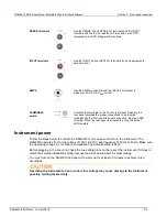
Страница 16: ...scriptions of the controls on the front panel follow the figure Figure 1 DMM6500 front panel POWER switch Turns the instrument on or off To turn the instrument on press and hold the power switch To turn it off press and hold the power switch again The LED is green when the instrument is on and the LED is amber when turned off HOME key Returns the display to the Home screen Section 2 Front panel ov...

Страница 17: ...2 drive Touchscreen The DAQ6510 has a high resolution five inch color touchscreen display The touchscreen accesses swipe screens and menu options You can access additional interactive screens by pressing the front panel MENU APPS and FUNCTION keys Refer to Touchscreen display on page 2 5 for details ENTER key Selects the highlighted choice or allows you to edit the selected field EXIT key Returns ...

Страница 18: ... the front panel terminals are active the green LED is visible When the rear panel terminals are active the amber LED is visible Instrument power Follow the steps below to connect the DAQ6510 to line power and turn on the instrument The DAQ6510 operates from a line voltage of 100 V to 240 V at a frequency of 50 Hz or 60 Hz Make sure the operating voltage in your area is compatible The default sett...

Страница 19: ...nals To prevent electrical shock that could cause injury or death remove power from the instrument or test system and discharge any energy storage components for example capacitors or cables before changing any connections that might allow contact with an uninsulated conductor On some sensitive or easily damaged devices under test DUTs the instrument power up or power down sequence can apply trans...

Страница 20: ...as tweezers or screwdrivers or pointed objects such as pens or pencils to touch the touchscreen It is strongly recommended that you use only fingers to operate the instrument Use of clean room gloves to operate the touchscreen is supported Select items on the touchscreen To select an item on the displayed screen Press the corresponding icon on the screen The following topics describe the DAQ6510 t...

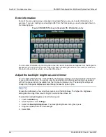
Страница 21: ...you touched the screen Adjust the backlight brightness and dimmer You can adjust the brightness of the DAQ6510 touchscreen display and buttons from the front panel or over a remote interface You can also set the backlight to dim after a specified time has passed with no front panel activity available from the front panel display only The backlight settings set through the front panel display are s...

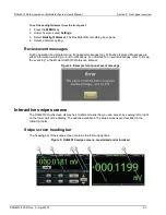
Страница 22: ...ly displayed Messages are either information warning or error notifications For information on event messages refer to Using the event log in the Model DAQ6510 Reference Manual Figure 4 Example front panel event message Interactive swipe screens The DAQ6510 touchscreen display has multiple screens that you can access by swiping left or right on the lower half of the display The options available i...

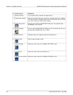
Страница 23: ...wipe screen without swiping 3 Calculations shortcut Select to open the CALCULATION SETTINGS menu Only available when TERMINALS is set to FRONT 4 Measure Settings shortcut Select to open the MEASURE SETTINGS menu for the selected function Only available when TERMINALS is set to FRONT 5 Restore indicator Indicates that you can swipe up to display the swipe screen 6 Graph shortcut Select to open the ...

Страница 24: ...tion Figure 6 FUNCTIONS swipe screen SETTINGS swipe screen The SETTINGS swipe screen gives you front panel access to some instrument settings for the selected measure function It shows you the present settings and allows you to change them The available settings depend on which measure function is active Figure 7 SETTINGS swipe screen To disable or enable a setting select the box next to the setti...

Страница 25: ...en the reading buffer is configured to fill continuously and overwrite old data with new data the buffer statistics include the data that was overwritten To get statistics that do not include data that has been overwritten define a large buffer size that will accommodate the number of readings you will make You can use the Clear Active Buffer button on this screen to clear the data from the active...

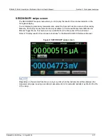
Страница 26: ...ion and select Secondary Measure Secondary measurements are only available in Continuous Measurement Mode and Manual Trigger Mode This feature is only available from the front panel of the instrument Refer to Display results of two measure functions in the Model DAQ6510 Reference Manual Figure 9 SECONDARY swipe screen Depending on the selected functions a relay may click when the instrument switch...

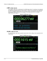
Страница 27: ... a test is in process Refer to Customizing a message for the USER swipe screen in the DAQ6510 Reference Manual This swipe screen is only displayed if custom text has been displayed Refer to Customizing a message for the USER swipe screen in the Model DAQ6510 Reference Manual Figure 10 USER swipe screen GRAPH swipe screen The GRAPH swipe screen shows a graphical representation of the readings in th...

Страница 28: ...w the graph in the full screen and to access graph settings select the graph icon on the right side of the swipe screen header You can also open the full function Graph screen by pressing the MENU key and selecting Graph under Views For more information about graphing measurements see Graphing in the Model DAQ6510 Reference Manual ...

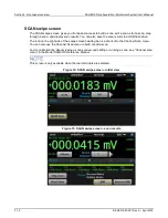
Страница 29: ... save the scan results to a USB flash drive The icon on the right side of the swipe screen heading bar is a shortcut to the Channel Scan menu You can also use the Channel Scan menu to build or edit a scan For more information about viewing a scan preview and editing or running a scan see Channel scan menu in the Model DAQ6510 Reference Manual This screen is only available when the rear terminals a...

Страница 30: ... following control options Button Description Build Scan Opens the SCAN screen where you can set up a new scan Edit Opens the SCAN screen where you can change the setup of a scan Save to USB Saves the data in the scan reading buffer toa CSV file on the USB flash drive Start Scan Runs a scan Step Scan Incrementally steps through a scan channel by channel ...

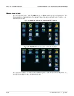
Страница 31: ...t panel The figure below shows the organization of the main menu The options change depending upon which set of terminals are selected front or rear Figure 14 DAQ6510 main menu front terminals selected Figure 15 DAQ6510 main menu rear terminals selected The main menu includes submenus that are labeled in green across the top of the display Selecting an option in a submenu opens an interactive scre...

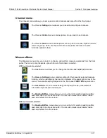
Страница 32: ...of terminals is selected With front terminals selected The QuickSet menu allows you to change the function and adjust performance The Measure Settings menu contains settings for the presently selected measure function which is identified by the function indicator in the upper right corner of the menu The available settings depend on the front panel FUNCTION key selection The Calculations menu cont...

Страница 33: ...ower part of the screen The Configure menu allows you to view and modify the structure and parameters of a trigger model You can also monitor trigger model operation Scripts menu The Scripts menus allow you to configure run and manage scripts from the front panel Scripts are blocks of commands that the instrument can run as a group The Run menu contains a list of scripts that you can select to run...

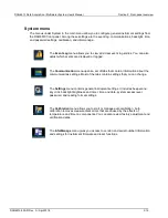
Страница 34: ...ation menu opens a set of tabs that contain information about the communications settings Most of the tabs contain settings that you can change The Settings menu contains general instrument settings It includes beeper and key click backlight brightness and timer time and date system access level password and reading format settings The Calibration menu allows you to start or manage auto calibratio...

Страница 35: ......

Страница 36: ... port on the rear panel of the instrument The GPIB RS 232 and TSP Link options require an optional accessory card In most cases you do not need to configure anything on the instrument In addition you do not need to reboot if you change the type of interface that is connected You can only use one communications interface to control the DAQ6510 at a time The USB connection takes precedence over LAN ...

Страница 37: ...etails about TSP Link see TSP Link System Expansion Interface in the Model DAQ6510 Reference Manual Figure 16 DAQ6510 remote interface connections LAN communications You can communicate with the instrument using a local area network LAN When you connect using a LAN you can use a web browser to access the internal web page of the instrument and change some of the instrument settings For more inform...

Страница 38: ...UNICATIONS window opens 3 Select LAN to see the settings for that interface 4 Press the EXIT key to leave the SYSTEM COMMUNICATION window without making any changes Set up automatic LAN configuration If you are connecting to a LAN that has a DHCP server or if you have a direct connection between the instrument and a host computer you can use automatic IP address selection If you select Auto the in...

Страница 39: ...r computer Do not change your IP address without consulting your system administrator If you enter an incorrect IP address it can prevent your computer from connecting to your corporate network or it may cause interference with another networked computer Record all network configurations before modifying any existing network configuration information on the network interface card Once the network ...

Страница 40: ...uter the VISA driver automatically detects the device Note that the VISA driver only automatically recognizes USBTMC and USBTMC USB488 devices It does not recognize other USB devices such as printers scanners and storage devices In this section USB instruments refers to devices that implement the USBTMC or USBTMC USB488 protocol Connect a computer to the DAQ6510 using USB To connect the DAQ6510 to...

Страница 41: ...ial number is also on the rear panel INSTR Use the USBTMC protocol To determine these parameters you can run the Keithley Configuration Panel which automatically detects all instruments connected to the computer If you installed the Keithley I O Layer you can access the Keithley Configuration Panel through the Microsoft Windows Start menu If you have a USB connection you cannot switch to a LAN con...

Страница 42: ...re 18 Select Communication Bus dialog box 4 Select USB 5 Click Next The Select Instrument Driver dialog box is displayed Figure 19 Select Instrument Driver dialog box 6 Select Auto detect Instrument Driver Model 7 Click Next The Configure USB Instrument dialog box is displayed with the detected instrument VISA resource string visible 8 Click Next The Name Virtual Instrument dialog box is displayed...

Страница 43: ...to the instrument 10 Select Finish 11 Select Cancel to close the Wizard 12 Save the configuration From the Keithley Configuration Panel select File Save Verify the instrument through the Keithley Communicator 1 Click Start Keithley Instruments Keithley Communicator 2 Select File Open Instrument to open the instrument you just named Figure 21 Keithley Communicator Open an Instrument 3 Click OK 4 Se...

Страница 44: ...will need a GPIB card Check the documentation for your GPIB controller for installation information and where to acquire drivers Install the KTTI GPIB accessory card Figure 22 KTTI GPIB connector view Unpack and inspect Make sure to handle the KTTI GPIB carefully Always grasp the card by the side edges Do not touch board surfaces components or areas adjacent to electrical contacts Contamination fr...

Страница 45: ...ounting screw Tighten these two screws either by hand or with a Phillips head screwdriver to secure the card in the case Do not overtighten 6 Reconnect the power line cable and any other cables to the rear panel 7 Turn on the instrument Connect GPIB cables to your instrument To connect a DAQ6510 to the GPIB interface use a cable equipped with standard GPIB connectors as shown below Figure 23 GPIB ...

Страница 46: ...stem User s Manual Section 3 Using a remote interface DAQ6510 900 01Rev A April 2018 3 11 Figure 24 DAQ6510 Instrument GPIB connections Additional information Additional information is available in the KTTI GPIB Accessory Installation Sheet ...

Страница 47: ...PIB address 5 Select OK You can also set the GPIB address using remote commands Set the GPIB address with the SCPI command SYSTem GPIB ADDRess or the TSP command gpib address RS 232 Install the KTTI RS232 accessory card Unpack and inspect Make sure to handle the KTTI RS232 carefully Always grasp the card by the side edges Do not touch board surfaces components or areas adjacent to electrical conta...

Страница 48: ...ounting screw Tighten these two screws either by hand or with a Phillips head screwdriver to secure the card in the case Do not overtighten 6 Reconnect the power line cable and any other cables to the rear panel 7 Turn on the instrument Making connections The RS 232 serial port can be connected to the serial port of a controller using a straight through RS232 cable terminated with DB 9 connectors ...

Страница 49: ...ust be installed on unused slots to prevent personal contact with high voltage circuits Failure to recognize and observe standard safety precautions could result in personal injury or death due to electric shock To install the communications card 1 Turn the instrument off and disconnect the power line cord and any other cables connected to the rear panel 2 Position the instrument so that you are f...

Страница 50: ...ID button to help you locate the instrument A virtual front panel and command interface that you can use to control the instrument Download access to a CSV file that contains reading buffer data Administrative options and LXI information The instrument web page resides in the firmware of the instrument Changes you make through the web interface are immediately made in the instrument Connect to the...

Страница 51: ...ethernet card The network card of the computer is enabled The IP address of the instrument is compatible with the IP address on the computer The subnet mask address of the instrument is the same as the subnet mask address of the computer There is a USB cable attached between the instrument and your computer USB communications take precedence over LAN You can also try restarting the computer and th...

Страница 52: ... page The Home page of the instrument provides information about the instrument It includes The instrument model number manufacturer serial number and firmware revision number The TCP Raw Socket number and Telnet Port number The last LXI message The history link opens the LXI Home page The ID button which allows you to identify the instrument Refer to Identify the instrument on page 3 18 ...

Страница 53: ...change the command set that you use with the DAQ6510 The remote command sets that are available include SCPI An instrument specific language built on the SCPI standard TSP A scripting programming language that contains instrument specific control commands that can be executed from a stand alone instrument You can use TSP to send individual commands or use it to combine commands into scripts SCPI27...

Страница 54: ...April 2018 3 19 To verify which command set is selected from a remote interface Send the command LANG To change to the SCPI command set from a remote interface Send the command LANG SCPI Reboot the instrument To change to the TSP command set from a remote interface Send the command LANG TSP Reboot the instrument ...

Страница 55: ......

Страница 56: ...nt Set the function before making other instrument settings Many of the settings are related to a specific measure function The applications in this manual use the order of operations to produce the best results Equipment required for this example Equipment required to perform this test One DAQ6510 Two insulated banana cables One resistor to test the example uses a resistor with a 9 75 kΩ rating S...

Страница 57: ...istor in a 2 wire local sense configuration In this configuration the device is connected between the INPUT HI and INPUT LO terminals To make the connections 1 Power off the DAQ6510 2 Connect the test leads to the front panel INPUT HI and INPUT LO terminals as shown in the following figure 3 Connect the test leads to the resistor Figure 29 DAQ6510 front panel 2 wire resistance measurement ...

Страница 58: ...om the front panel 1 Press the POWER switch on the front panel to turn on the instrument 2 Make sure the terminals switch is set to FRONT 3 From the Functions swipe screen select 2W Ω Measurements begin to display on the top half of the Home screen 4 If measurements are not displayed press the TRIGGER key for a few seconds and select Continuous Measurement To change the measure settings 1 Press th...

Страница 59: ...eading table displays Front If you are using the REAR terminals the Channel column displays Rear If you are using a card the Channel column displays the channel number 3 To display data for a different reading buffer select the buffer 4 To view details for a specific data point swipe the table up or down and select the data point to view the Reading Details If there are many data points select an ...

Страница 60: ... chamber and exposed to extreme conditions The system captures data at different locations on the DUT The data is then exported from the DAQ6510 to a computer where a thermal profile is generated This thermal profile provides designers and consumers with a thorough understanding of the thermal operating characteristics of their device or product Equipment required One DAQ6510 One Model 7700 20 cha...

Страница 61: ...e 7700 from the DAQ6510 3 Remove the top cover from the 7700 Figure 32 Screw terminal access 4 Connect ten Type K thermocouples to each channel as shown Figure 33 7700 multiplexer module thermocouple connections 5 Route the cables out through the channels in the 7700 and secure the top cover 6 Ensure that the DAQ6510 power is turned off 7 Insert the 7700 into a slot on the rear of the DAQ6510 Figu...

Страница 62: ...sis ground screw terminal on the rear panel Note that the front panel terminals are isolated from the rear panel terminals Therefore if you are using the front panel terminals ground to the front panel LO terminal If using the rear panel terminals ground to the rear panel LO terminal Failure to follow these guidelines can result in injury death or instrument damage Thermocouple temperature scannin...

Страница 63: ...Junction to Internal 8 Select the Scan tab set the Scan Count to 1440 and select OK One scan every minute for 24 hours 24 hours 60 minutes 1440 9 Set the Interval Between Scans to 60 s and select OK 10 Scroll down on the Scan tab to Export to a USB flash drive Choose After Each Scan from the list of options 11 Select Filename enter scan24hr and select OK to accept 12 Select OK to accept the remain...

Страница 64: ...101 110 Set up channel settings for Slot 1 SENSe TEMPerature TRANsducer TCouple 101 110 SENSe TEMPerature TCouple TYPE K 101 110 SENSe TEMPerature TCouple RJUNction RSELect INTernal 101 110 SENSe TEMPerature ODETector ON 101 110 ROUTe SCAN CREate 101 110 Set up Scan ROUTe SCAN COUNt SCAN 1440 Set the scan count to 24 hrs 60 min hr 1440 ROUTe SCAN INTerval 60 0 Set the time between scans to 60 s RO...

Страница 65: ...P commands makes a series of temperature measurements After the code executes the data is displayed in the Instrument Console of Test Script Builder Send the following commands for this example application Reset the instrument to the default settings reset Set up channel settings for Slot 1 channel setdmm 101 110 dmm ATTR_MEAS_FUNCTION dmm FUNC_TEMPERATURE channel setdmm 101 110 dmm ATTR_MEAS_TRAN...

Страница 66: ...ntal progress bar is completely green when the connections at the screw terminals and at the DUT are secure The SCAN swipe screen provides the time remaining in seconds and the scan countdown Figure 35 DAQ6510 scan start screen 2 If you have data on the USB flash drive and want to review it prior to completion pause the scan remove the drive copy the data file to your PC return the drive to the DA...

Страница 67: ...ual 5 8 DAQ6510 900 01Rev A April 2018 3 Once the scan is complete the SCAN swipe screen provides you with additional options You can select different tabs that provide graphical data analysis options The following figure shows a sample graph for this application Figure 37 DAQ6510 graph UI four views png ...

Страница 68: ...line frequency seconds The more AC line cycles used in the measurement the more accurate the reading The time required to conduct the scan also increases The autozero function removes offset voltages that result from thermal EMFs Thermal EMFs occur when there is a temperature difference at junctions consisting of different materials For example leads instrument inputs or card terminals These EMFs ...

Страница 69: ...uses a DAQ6510 with a 7700 multiplexer module In this example channels 101 to 106 are connected to six DUTs device under test where DC voltage is measured Figure 38 DAQ6510 instrument and devices connections for low level DCV Connecting devices to the instrument 1 Power off the DAQ6510 2 Remove the 7700 from the DAQ6510 3 Remove the top cover from the 7700 ...

Страница 70: ...S can appear on LO terminals This can occur when the instrument is operating in any mode To prevent hazardous voltage from appearing on the LO terminals connect the LO terminal to protective earth safety ground if your application allows it You can connect the LO terminal to the chassis ground terminal on the front panel or the chassis ground screw terminal on the rear panel Note that the front pa...

Страница 71: ...ottom of the left pane To watch active readings during scan 1 Press the HOME key 2 Select the arrow to the right of Watch Channel 3 Select the channels of interest and select OK to accept To save the scanned measurements to a USB flash drive 1 Select the MENU key 2 Under the Measure column choose Reading Buffers 3 Insert a USB flash drive into the DAQ6510 Select Save to USB at the bottom of the pa...

Страница 72: ...lt buffer but added to show command use case ROUT SCAN BUFF defbuffer1 Assign all scanned data to defbuffer1 FUNC VOLT DC 101 106 Set channels functions to DCV VOLT DC RANG AUTO ON 101 106 Set the channels ranges to auto VOLT DC NPLC 5 101 106 Set NPLC to 5 VOLT DC AZER ON 101 106 Set autozero function to ON ROUT SCAN 101 106 Setup the scan list ROUT SCAN COUN SCAN 10 Setup the number of repeated ...

Страница 73: ...s 3 Set the Command Set to TSP 4 At the prompt to reboot select Yes This sequence of TSP commands initiates a series of temperature measurements After the code executes the data is displayed in the Instrument Console of Test Script Builder Send the following commands for this example application Reset the instrument to the default settings reset channelCount 6 scanCount 10 bufferSize channelCount ...

Страница 74: ...r low resistance measurements With this configuration the test current is sourced through the DUT using one set of test leads while a second set of SENSE leads measures the voltage across the DUT The voltage sensing leads are connected as close to the device under test as possible to avoid including the resistance of the test leads in the measurement Thermoelectric voltages EMFs can seriously affe...

Страница 75: ...tem User s Manual 7 2 DAQ6510 900 01Rev A April 2018 Equipment required One DAQ6510 One Model 7700 20 channel differential multiplexer module One computer set up for communication with the instrument Six resistors of 100 Ω 68 Ω 10 Ω 2 2 Ω 0 5 Ω and 0 2 Ω One device or component to be tested ...

Страница 76: ...annels on a 7700 multiplexer module For this example you will Configure channels 101 102 103 104 105 and 106 to measure resistors in this case 100 Ω 68 Ω 10 Ω 2 2 Ω 0 5 Ω and 0 2 Ω Pair channels 111 to 116 with channels 101 to 106 respectively to provide the SENSE connections needed for 4 wire measurement Select fixed ranges and apply offset compensation to each channel Execute 100 scans for all s...

Страница 77: ...event contact with test leads There is no internal connection between protective earth safety ground and the LO terminals of the DAQ6510 Therefore hazardous voltages more than 30 Vrms can appear on LO terminals This can occur when the instrument is operating in any mode To prevent hazardous voltage from appearing on the LO terminals connect the LO terminal to protective earth safety ground if your...

Страница 78: ...channel 101 by selecting 4 Wire Res 10 Under the Settings tab select Range and set to 100 W 11 Select chanel 102 by selecting 4 Wire Res and set the Range to 100 W 12 Select chanel 103 by selecting 4 Wire Res and set the Range to 10 W 13 Select chanel 104 by selecting 4 Wire Res and set the Range to 10 W 14 Select chanel 105 by selecting 4 Wire Res and set the Range to 1 W 15 Select chanel 106 by ...

Страница 79: ...g commands for this example application Commands Descriptions RST Reset the DAQ6510 ROUT SCAN COUN SCAN scanCnt Set the number of times the scan is repeated FUNC FRES 101 106 Set function to 4 wire measurement FRES OCOM ON 101 106 Set offset compensation to on FRES RANG 100 101 102 Set the fixed range at 100 Ω FRES RANG 10 103 104 Set the fixed range at 10 Ω FRES RANG 1 105 106 Set the fixed range...

Страница 80: ...t Settings 3 Set the Command Set to TSP 4 At the prompt to reboot select Yes This sequence of TSP commands initiates a series of temperature measurements After the code executes the data is displayed in the Instrument Console of Test Script Builder After the scan the data in the buffer is stored on a USB flash drive Send the following commands for this example application Reset the instrument to t...

Страница 81: ...the six resistors listed in the Instrument and Device Connection section The data provided in each cell of the table is the average of 100 scans Nominal value Ω Four wire measurement with offset compensation Ω Four wire measurement with NO offset compensation Ω Two wire measurement Ω 100 98 3242 98 3206 98 5831 68 67 9920 68 0080 67 2703 10 10 00998 10 00141 10 28680 2 2 2 20413 2 20588 2 51011 0 ...

Страница 82: ...ed into a test stand Wired to a fixture that is connected to an active device under test DUT Quickly capturing DC volts and current temperature and AC volts and current Prior to the start of the scan you can step through each of the configured channels on the DAQ6510 which allows you to troubleshoot the test configuration This allows you to view the readings of individually closed channels to ensu...

Страница 83: ...rmocouples of two voltage regulators within the DUT Channels 113 to 114 Temperature using Type K thermocouples of two loads to which the DUT is supplying power Channel 121 AC current being drawn by the DUT Channel 122 DC current being drawn by the load Figure 41 DAQ6510 Model 7700 To prevent electric shock test connections must be configured such that the user cannot come in contact with test lead...

Страница 84: ...anel LO terminal If using the rear panel terminals ground to the rear panel LO terminal Failure to follow these guidelines can result in injury death or instrument damage Mixed function multi channel scanning This application example uses the DAQ6510 to execute complex multi channel mixed function scanning in a production test environment For this application you will Configure the instrument for ...

Страница 85: ...or the Reference Junction 14 In the top left corner of the screen select Menu select Expand Groups 15 Select channel 111 and enter Reg12VTemp for the label Select OK 16 Select channel 112 and enter Reg5VTemp for the label Select OK 17 Select channel 113 and enter LoadTemp1 for the label Select OK 18 Select channel 114 and enter LoadTemp2 for the label Select OK 19 Select Menu and Collapse Groups T...

Страница 86: ...andwidth to 30Hz SENS FUNC VOLT DC 102 110 Set channels 102 110 for DCV SENS FUNCtion TEMPerature 111 114 Set channels 111 114 for Temperature measurement using Type K thermocouples with a simulated reference junction set to 23 C SENS TEMP TRAN TC 111 114 SENS TEMP TC TYPE K 111 114 SENS TEMP TC RJUN RSEL SIM 111 114 SENS TEMP TC RJUN SIM 23 111 114 SENS FUNC CURR AC 121 Set channel 121 to measure...

Страница 87: ... the following commands for this example application Reset the instrument to the default settings reset Establish channel settings for the scan card configuration channel setdmm 101 dmm ATTR_MEAS_FUNCTION dmm FUNC_AC_VOLTAGE channel setdmm 101 dmm ATTR_MEAS_DETECTBW dmm DETECTBW_30HZ channel setdmm 102 110 dmm ATTR_MEAS_FUNCTION dmm FUNC_DC_VOLTAGE channel setdmm 111 114 dmm ATTR_MEAS_FUNCTION dmm...

Страница 88: ... 3 Scroll the reading table noting both the measurements and labels in the Channel column of the table Figure 42 DAQ6510 reading table mixed function multichannel scanning To save the scanned measurements to a USB flash drive 1 Select the MENU key 2 Under the Measure column choose Reading Buffers 3 Insert a USB flash drive into the DAQ6510 select Save to USB 4 Select the Change button adjacent to ...

Страница 89: ......

Страница 90: ...module uses reed relays which have low contact resistance 1 Ω through the end of life but a higher contact potential 6 µV max which contributes more signal offset and slightly less precise readings The benefit of this module is shorter relay close time less than 1 ms which makes it approximately three times faster than the 7700 The 7710 multiplexer module uses solid state relays which have the hig...

Страница 91: ...original factory setup The GPIB interface requires an optional communications accessory See the following image for the connection example Figure 43 DAQ6510 speed scanning instrument and device connection The 7700 replaces the 7710 for the second run of the program code for comparison and assumes the same input signals to channels 101 to 120 To prevent electric shock test connections must be confi...

Страница 92: ...ut This application demonstrates how to configure the DAQ6510 to execute scans at the best scan speed You will eliminate certain measurement options that add to overall test time The scan completion times of the 7700 and 7710 20 channel differential multiplexer modules will be compared and you will see the speed improvement attributed to solid state relays over electromechanical relays used in som...

Страница 93: ...f readings int chanCnt Create a variable to hold the channel count int actualRdgs Create a variable to hold the actual reading count string rcvBuffer Create a string buffer to hold extracted readings timer1 start Start a timer to help capture elapsed time DAQ6510 RST Put the instrument in a known state FORM DATA ASCII Format data as an ASCII string ROUT SCAN COUN SCAN scanCnt Apply the scan count ...

Страница 94: ...eCnt but leave the incrementing of i for later delay 500 Delay for 500 ms to allow readings to accumulate DAQ6510 actualRdgs TRACe ACTual Query the actual readings captured rcvBuffer TRACe DATA i actualRdgs defbuffer1 READ Query the readings available from i to the value of actualRdgs Pseudocode WriteReadings C myData csv rcvBuffer Write the extracted readings to a file myData csv on the local com...

Страница 95: ...the data is displayed in the Instrument Console of Test Script Builder Send the following commands for this example application Set up variables to be referenced during the scan scanCnt 1000 sampleCnt 0 chanCnt 0 actualRdgs 0 rcvBuffer Get the initial timestamp for end of run comparison local x os clock Reset the instrument and clear the buffer reset defbuffer1 clear Set up reading buffer format a...

Страница 96: ...tstate display STATE_LCD_50 Output the elapsed time to the user print string format Elapsed Time 2f n os clock x Test results Factory run times are as follows The test time for an equivalent setup using the Model 7703 has also been provided so that you can see what is achievable with the reed relays Differential Multiplexer Module Setup Outcome 7710 20 channels for 1000 scans at 20 000 readings Ap...

Страница 97: ......

Страница 98: ...een scans The DAQ6510 can monitor the environment until the target temperature has been reached at which point the instrument automatically begins the scan This application example demonstrates how to use a DAQ6510 to initiate a scan based on the temperature of the environment around the device under test DUT This example will model a situation where resistance DUTs are measured after the temperat...

Страница 99: ...proper shields barriers and grounding to prevent contact with test leads There is no internal connection between protective earth safety ground and the LO terminals of the DAQ6510 Therefore hazardous voltages more than 30 VRMS can appear on LO terminals This can occur when the instrument is operating in any mode To prevent hazardous voltage from appearing on the LO terminals connect the LO termina...

Страница 100: ...l select Scan 5 Select the button to add a group of channels 101 to 105 and select OK 6 Select 2W Resistance on the Measure Functions screen 7 In the upper left corner of the screen select Expand Group from the Menu icon 8 Select channel 101 by selecting the adjacent 2 Wire Res button Change the function to Temperature 9 Set Reference Junction to Internal 10 In the Scan tab change the Scan Count t...

Страница 101: ...e FUNC TEMP 101 Monitor temperature on channel 101 TEMP TRAN TC 101 Set transducer type to thermocouple TEMP TC TYPE K 101 Set thermocouple type to K TEMP UNIT CELS 101 Set unit to Celsius TEMP TC RJUN RSEL INT 101 Set internal reference ROUT SCAN MON CHAN 101 Monitor channel 101 ROUT SCAN MON LIM UPP 30 Set upper limit to 30 Celsius degree ROUT SCAN MON MODE UPP Set monitor mode to upper FUNC RES...

Страница 102: ...uence of TSP commands monitors the temperature measurement on the first channel to ensure the test environment has reached the required temperature to begin scanning After the code executes the data is displayed in the Instrument Console of Test Script Builder Send the following commands for this example application monitor temperature on channel 101 reset channel setdmm 101 dmm ATTR_MEAS_FUNCTION...

Страница 103: ......

Страница 104: ...elps you find answers to the most common questions encountered with the DAQ6510 Where can I find updated drivers For the latest drivers and additional support information see the Keithley Instruments support website To see what drivers are available for your instrument 1 Go to tek com keithley 2 Enter the model number of your instrument 3 Select Software Driver from the list If you use the native ...

Страница 105: ...f the flash drive and must be the only firmware file in that location You can upgrade or downgrade the firmware from the front panel or from the virtual front panel From the front panel or virtual front panel 1 Copy the firmware file upg file to a USB flash drive 2 Verify that the firmware file is in the root subdirectory of the flash drive and that it is the only firmware file in that location 3 ...

Страница 106: ...uage built on the SCPI standard TSP A scripting programming language that contains instrument specific control commands that can be executed from a stand alone instrument You can use TSP to send individual commands or use it to combine commands into scripts SCPI2700 An instrument specific language that allows you to run code developed for Keithley Instruments Series 2700 instruments SCPI2701 An in...

Страница 107: ...sh drive From the front panel 1 Configure the DAQ6510 to the settings that you want to save 2 Press the MENU key 3 Under Scripts select Save Setup The SAVE SETUP window is displayed 4 Select Create A keyboard is displayed 5 Use the keyboard to enter the name of the script 6 Select the OK button on the displayed keyboard The script is added to internal memory Using SCPI commands Configure the instr...

Страница 108: ...ve when you set them For example assume you have the measure function set to current and you set a value for display digits When you change the measure function to voltage the display digits value changes to the value that was last set for the voltage measure function When you return to the current measure function the display digits value returns to the value you set previously What is the ethern...

Страница 109: ......

Страница 110: ...additional information about the instrument From the website you can access The Knowledge Center which contains the following handbooks The Low Level Measurements Handbook Precision DC Current Voltage and Resistance Measurements Switching Handbook A Guide to Signal Switching in Automated Test Systems Application notes Updated drivers Information about related products Your local Field Applications...

Страница 111: ......

Страница 112: ...rranty 1 2 Extended warranty 1 2 F front panel interface 2 1 using 2 1 Front panel overview 1 3 2 1 FUNCTIONS swipe screen 2 9 G GPIB Install 3 9 GPIB communications 3 9 GRAPH swipe screen 2 12 H How do I change the command set 11 3 How do I save the present state of the instrument 11 4 How do I upgrade the firmware 11 2 I Identify the instrument 3 17 3 18 Install the KTTI GPIB accessory card 3 9 ...

Страница 113: ... scanning for increased production test throughput 9 3 Speed scanning for increased test throughput 9 1 STATISTICS swipe screen 2 10 Supported remote interfaces 3 2 Swipe screen heading bar 2 7 System menu 2 19 T Test results 5 7 7 8 8 7 9 7 Thermocouple temperature scanning 5 3 Touchscreen display 2 2 2 5 Trigger menu 2 18 Troubleshooting FAQ 1 3 11 1 TSP 3 18 TSP Link 3 14 Turn the DAQ6510 on or...

Страница 114: ...ions are subject to change without notice All Keithley trademarks and trade names are the property of Keithley Instruments All other trademarks and trade names are the property of their respective companies 12 17 ...

Отзывы: