background image

GB - 6

Unauthorised opening and tampering may lead to bodily injury and property damage 

and may entail the loss of warranty rights. Original spare parts and authorized accesso-

ries by the manufacturer serve as security. The use of other parts excludes liability for 

the consequences arising out of.

The suspension of liability is especially valid also for operation interruption loss, loss of 

profit, data loss or other damages. This is also valid, if we referred first to the possibility 

of such damages.

If single regulations should be or become void, invalid or impracticable, the effectivity of 

all other regulations or agreements is not affected.

1.4 Copyright

The customer may use the instruction manual as well as further documents or parts from 

it for internal purposes. Copyrights are with KEB and remain valid in its entirety. All rights 

reserved.

KEB

®

, COMBIVERT

®

, COMBICONTROL

®

 and COMBIVIS

®

 are registered trademarks of 

Karl E. Brinkmann GmbH.

Other wordmarks or/and logos are trademarks (™) or registered trademarks (®) of their 

respective owners and are listed in the footnote on the first occurrence.

When creating our documents we pay attention with the utmost care to the rights of third 

parties. Should we have not marked a trademark or breach a copyright, please inform 

us in order to have the possibility of remedy.

Preface

Содержание COMBIVERT R5-C

Страница 1: ...COMBIVERT GB Instruction Manual Power Supply R5 C V1 1 Mat No Rev 00R50EB K001 1C ...

Страница 2: ......

Страница 3: ...7 2 3 Unit identification 7 2 4 Technical data 8 3 Installation 9 3 1 Unit Installation 9 3 1 1 Dimensions 9 3 1 2 Installation Instructions 9 3 2 Connection of the Power Unit 10 3 2 1 Mains Connection of the Supply Unit 10 3 2 2 Terminal strips of the power circuit 11 3 2 3 Connection of a braking resistor 12 3 2 4 Connection of a Temperature Detection 13 3 3 Instructions of an EMC conform Instal...

Страница 4: ...assword input 18 5 4 Parameter description 19 6 Functional Description 21 6 1 Block Diagram of the Supply Unit 21 6 2 Switch on procedure 21 6 3 Power Off the Supply Unit 21 6 4 Error During Operation 22 6 5 Braking option 22 6 6 Flow charts 22 6 6 1 Power on with Normal Conditions 23 6 6 2 Ground Fault during Power on to DC 24 6 6 3 Charge Time Exceeding during Power on 25 6 6 4 Output error duri...

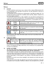
Страница 5: ...This list is not exhaustive 1 2 Safety instructions Observe safety and operating instruc tions Precondition for all further steps is the knowledge and observance of the safety and operating instructions This is provided accompanied by the device or by the download site of www keb de Non observance of the safety and operating instructions leads to the loss of any liability claims The warnings and s...

Страница 6: ... impracticable the effectivity of all other regulations or agreements is not affected 1 4 Copyright The customer may use the instruction manual as well as further documents or parts from it for internal purposes Copyrights are with KEB and remain valid in its entirety All rights reserved KEB COMBIVERT COMBICONTROL and COMBIVIS are registered trademarks of Karl E Brinkmann GmbH Other wordmarks or a...

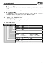
Страница 7: ...tric consumers is prohibited and can lead to the destruction of the unit 2 2 Features of the COMBIVERT R5 C Degree of protection IP20 Extensive protection against overcurrent ground fault and temperature Short circuit proof with corresponding dimensioned mains fuses 2 3 Unit identification Product description 2 3 R 5 C 1 R 9 0 R 0 Cooling A default Version 0 default free 0 default Voltage 9 3ph 40...

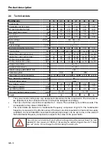
Страница 8: ... 29 Housing size R R R U U U Chargeable inverter power 1 kW 30 75 110 160 200 250 DC nominal output current ADC 90 180 270 380 470 610 Max short time current 2 AAV 135 270 405 570 705 915 OL current ADC 153 306 459 646 799 1037 Input current 3 ARMS 79 8 147 5 221 312 386 500 Mains voltage V ACRMS 305 504 0 Phases 3 Output voltage V DC 430 713 Maximal permissible mains fuse A 100 200 350 500 710 71...

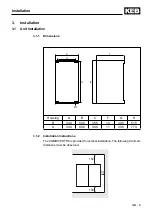
Страница 9: ... Instructions The COMBIVERT R5 is provided for vertical installation The following minimum distances must be observed 30 150 100 3 Installation 3 1 Unit Installation 3 1 1 Dimensions Housing A B C F G H R 340 545 355 10 300 515 U 340 800 408 11 300 774 ...

Страница 10: ... of interconnected operation with several supply units consider information sheet 00 R5 0DM I000 Switching at the input without waiting of an under potential error E UP causes high wear of the switching contacts Fuses and overcurrent protection units can release furthermore See publication ENG 000 0001 Connection of the supply unit ...

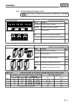
Страница 11: ...able 3 2 2 1 T1 T2 PB PA Name Function No L1 L2 L3 3 phase mains connection 1 DC link output PA PB Connection for braking resistor 2 L2 L3 L1 T1 T2 Connection for temperature sensor 3 Connection for shielding earthing 4 Table3 2 2 1 Permissible cable cross sections and tightening torques of the terminals No permissible cross section flexible with wire end ferrule Max tightening torque mm AWG MCM N...

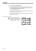
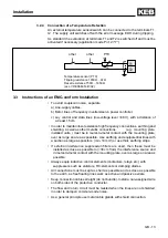
Страница 12: ...urrent of the brake transistor is monitored additionally The input thyristors are switched off in case of a short circuit Braking resistors can develop a very high surface temperatures therefore install as safe to touch as possible 3 2 3 Connection of the Braking Resistor Connection of a braking resistor As standard the evaluation at terminals T1 and T2 is switched off and must be activated if nec...

Страница 13: ...mounting plate installed units must be in metal to metal contact with the mounting plate over as large an area as possible Use earthing and equipotential lines with a section as large as possible min 10mm2 or use thick earthing strips If external interference suppression filters are used then these must be installed as close as possible to 30cm from the interference source and in metal to metal co...

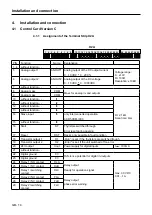
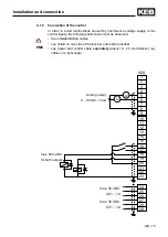
Страница 14: ...ected operation 00 R5 0DM I000 15 without function I6 16 Start ST Thyristors switched through Error reset during opening 17 Reset RST Reset only possible in fault condition 18 Transistor output 1 O1 Run is set if the thyristors are switched trough 19 Transistor output 2 O2 Error is set if the unit switched off on error 20 24V output Uout Power supply for digital inputs Imax 100mA 21 without functi...

Страница 15: ...lowing instructions must be observed Use shielded drilled cables Lay shield on one side of the inverter onto earth potential Lay power and control cable separately about 10 20 cm distance lay cables in a right angle EMC max 30VDC 0 01 1A max 30VDC 0 01 1A max 50mA DC for both outputs Analog output 0 10VDC 5mA Installation and connection ...

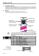
Страница 16: ...rface for the serial data transfer to RS232 485 The direct connection PC to the inverter is only valid with a special cable HSP5 PartNo 00 F5 0C0 0001 otherwise it would lead to the destruction of the PC interface 5 4 3 2 1 9 8 7 6 Double function keyboard Status Error display Normal LED on Error LED blinks Interface check BUS operation LED on only 00 F5 060 2000 5 digit LED display RS232 RS485 on...

Страница 17: ...ration the actual display is overwritten by the alarm message The alarm message in the display is reset by ENTER With ENTER only the error message in the display is reset In order to reset the error itself the cause must be removed or a power on reset must be made In the status display CP 1 the error will still be shown Operation of the Unit FUNC SPEED The function key is used to change between pa...

Страница 18: ...ing the inverter can be secured against unauthorized access The adjusted mode is stored Display Parameter Setting range Resolution Fact setting CP 0 Password input 0 9999 1 CP 1 Status display CP 2 AC input current 0 1A CP 3 DC output current 0 1A CP 4 DC output current peak value 1 CP 5 current DC utilization 1V CP 6 current DC voltage 1V CP 7 DC output voltage 1V CP 8 DC output voltage peak valu...

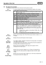
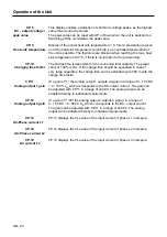
Страница 19: ... compared all 4ms with the average value of the effective input currents CP 2 If after triple scanning 12ms a difference of 15 of one phase to CP 2 is detected then a prewarning is released and switched off after 60s if the difference is 50 immedeiately switched off if the difference is 50 CP 2 AC current Display of the average value of the effective input currents of phase L1 L3 in ampere CP 3 DC...

Страница 20: ... exceeded in case of very large capacities the charge time can be extended up to 500 with the charge time factor CP 11 Analog output 1 gain At a gain of 1 the analog output 1 outputs a signal in a range of 0 10VDC 0 150 IDC which corresponds to the DC output current The gain can be adjusted with CP 11 in a range of 20 00 The analog output can be adapted thereby to individual requirements CP 12 Ana...

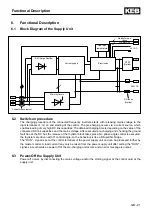
Страница 21: ...ngle control is executed the thyristors are driven with 0 control angle so the behaviour is like a B6 rectifier bridge The RUN signal is set at the control terminals of the power supply unit and can be processed further by the master control A load current may only be taken from the power supply unit after setting the RUN signal since otherwise a power off of the pre charging unit occurs and an er...

Страница 22: ...is given out if the heat sink temperature is too high so a controlled deceleration of the unit is possible The thyristors are blocked when reaching the max heat sink temperature of 90 C if there is no reaction to the pre warning 6 5 Braking option The brake transistor is controlled with a DC link voltage starting from 740 VDC 6 6 Flow charts On the following pages there are some flow charts for a ...

Страница 23: ...s Status Output ready Output run 1 0 1 0 UDC Precharge Precharge 1 0 1 0 Thyristor 1 0 1 0 Output error Power off nOP GF Test charge run du 50V CP 6 Actual DC Voltage CP 7 DC Output Voltage t 104ms t 24ms t t t t t t t t Functional Description ...

Страница 24: ... 24 6 6 2 Ground Fault during Power on to DC Status Output ready Output run Output error Precharge Precharge Power off nOP GF Test E GF1 t t t t t 1 0 1 0 1 0 1 0 1 0 1 0 Thyristor Functional Description ...

Страница 25: ...ng Power on Status Output ready Output run 1 0 1 0 Output error 1 0 UDC Precharge 1 0 Thyristor 1 0 Power off nOP GF Test charge Error charge time out du 50V CP 6 Actual DC Voltage CP 7 DC Output Voltage t t t t t t t Functional Description ...

Страница 26: ... error during Operation Status Output ready Output run Output error UDC Thyristor 1 0 1 0 1 0 0 1 0 1 0 CP 6 Actual DC Voltage CP 7 DC Output Voltage du 200V run Error rectifier output t t t t t t Functional Description ...

Страница 27: ...one phase to CP 13 is detected then at ru 13 50 a warning is triggered and switched off after 60 s status E UPh at ru 13 50 is immediately switched off status E UPh t t t t t t t t 60s max Status IAC 0 5 In Output ready 1 0 Output run 1 0 Output warning 1 0 Output error 1 0 Thyristor 1 0 run phase failure occurs Error phase failure Functional Description ...

Страница 28: ...3 899 2035 mail vb espana keb de Société Française KEB Z I de la Croix St Nicolas 14 rue Gustave Eiffel 94510 LA QUEUE EN BRIE fon 33 1 49620101 fax 33 1 45767495 net www keb fr mail info keb fr KEB UK Ltd Morris Close Park Farm Industrial Estate Wellingborough NN8 6 XF fon 44 1933 402220 fax 44 1933 400724 net www keb co uk mail info keb co uk KEB Italia S r l Via Newton 2 20019 Settimo Milanese ...

Отзывы: