


NTCL (Non-Timed Current Limit) –
When jumper J3 is set to “NTCL” position, the con-
trol will not go into “STOP” after it is in overload.
Note:
TCL trimpot will have no affect when jumper J3 is in “NTCL” position.
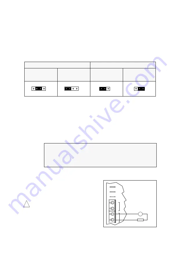
D. DC Tach-Generator Voltage Selection (J1 and J4) –
For a tach-generator wired to TB3,
set jumper J1 to “T” position. See Figure 16. Jumper J4 is factory set to “7V” position for
7 Volt per 1000 RPM tach-generators wired to TB3. For a 50 Volt per 1000 RPM tach-
generator, set jumper J4 to “50V” position.
Note:
When using a tach-generator, the IR trimpot should be set fully counterclockwise.
Note:
The tach-generator input is designed for 7 Volt or 50 Volt per 1000 RPM tach-
generators used with 1800 RPM motors. For tach-generators other than 7 Volt or 50 Volt
per 1000 RPM or for motors other than 1800 RPM, an external 1/2 watt resistor (R
T
) must
be used. Install R
T
in series with the tach-generator as shown in Figure 17. Jumper J4
must be set to “7V” position.
The value of R
T
in Ω can be calculated using the following formula:
R
T
= (1.46 x V
T
x S) - 19,000
Where V
T
is the tach-generator voltage (in Volts per 1000 RPM) and S is the base speed
of the motor (in RPM).
Example:
E. Run Relay Output Mode Selection (J5) –
Jumper J5 is factory set to “NO” position for nor-
mally open relay output at TB4. For normally
closed relay output, set jumper J5 to “NC” posi-
tion. See Figure 18, on page 12.
V.
MOUNTING INSTRUCTIONS
Warning! The KBPW-240D is not designed to
be used in an explosion-proof application.
It is recommended that the control be mounted verti-
cally on a flat surface with adequate ventilation.
Leave enough room below the control to allow for AC
line, motor connections, and any other wiring.
Although the control is designed for outdoor and
washdown use, care should be taken to avoid extreme hazardous locations where physical
damage can occur. If the control is mounted in a closed, unventilated location, allow enough
room for proper heat dissipation. If operating the control at full rating, a minimum enclosure
size of 12”W x 24”H x 12”D is required. See Figure 2, on page 5.
11
Suppose you have a 20 Volt per 1000 RPM tach-generator with a 3600 RPM motor:
R
T
= (1.46 X 20 X 3600) - 19000 = 86120Ω.
Choose the closest 1/2W resistor value, which is 82000Ω (82kΩ) or 91000Ω (91kΩ).
Readjustment of the MAX trimpot may be necessary to achieve the desired maximum
output voltage.
50V
7V
7V 50V
90V
180V
T
J1
J4
J4
90V
J1
180V
T
J1 Set for 90 Volt Motors
(Factory Setting)
J4 Set for 7V per 1000RPM
Tach-Generator Input
(Factory Setting)
J4 Set for 50V per 1000RPM
Tach-Generator Input
J1 Set for
Tach-Generator Input
Jumper J1 Settings
Jumper J4 Settings
FIGURE 16 – DC TACH-GENERATOR VOLTAGE SELECTION
T
G
R
DC TACH-GENERATOR
+
-
TACH
RELAY
P1
K1
K2
T+
T-
TB3
TB4
P2
P3
FIGURE 17 – DC TACH-GENERATOR
WITH ADDITION OF R
T
!