


G. Remote Start/Stop Switch Connections –
The control is supplied with a prewired
Start/Stop switch mounted on the front cover. To operate the control from a remote
Start/Stop switch (type: (ON)-OFF-ON, SPDT), remove the white, black, and red wires
from START, COM, and STOP terminals,
respectively. The leads may be taped and
left in the control. The switch itself may be
removed if a watertight seal is used to
cover the hole in the front cover. Connect
the remote Start/Stop switch wires to
START (momentary), COM (common),
and STOP (constant) terminals as shown
in Figure 7. After applying power, momen-
tarily set the Start/Stop switch to “START”
position. The motor will operate at the set
speed of the main speed potentiometer.
To stop the motor, set the Start/Stop
switch to “STOP” position.
Note:
To eliminate the Start/Stop function, connect the START and COM terminals with
the jumper that is provided.
CAUTION!
Eliminating the Start/Stop function using a jumper will cause the motor to run
at the main speed potentiometer setting when the AC line is applied.
H. Run Relay Connection –
Normally open (NO) or normally closed (NC) relay output con-
tacts are available at TB4, which will change state when the Start/Stop switch is set to
“START” position or if the control shuts down and goes into STOP mode from TCL. The
run relay is used to indicate the state of the control (run or stop). Normally open or nor-
mally closed run relay contact outputs can be selected depending on the position of
jumper J5. If normally open is selected (J5 in “NO” position), the run relay output contacts
will close when the Start/Stop switch is set to “START” position. If normally closed is
selected (J5 set to “NC” position), the run relay output contacts will open when the
Start/Stop switch is set to “START” position. When the control shuts down and goes into
STOP mode from TCL, or the Start/Stop switch is set to “STOP” position, the Run Relay
output contacts will return to their normal position.
Note:
If relay output contacts are not required
for your application, J5 may be in any position.
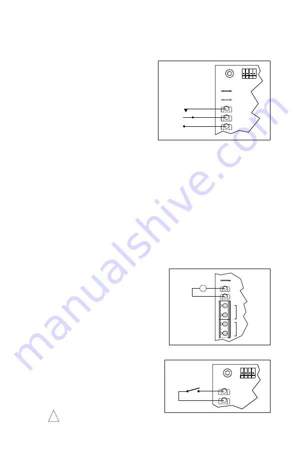
I. Voltage Following Connection –
An isolated
0 - 10 Volt DC analog signal can also be used
to control motor speed. See Figure 8.
Note:
If an isolated signal voltage is not avail-
able, an optional signal isolator can be
installed (KBSI-240D, P/N 9431). Connect the
isolated signal voltage to P2 (+) and P1 (-) ter-
minals. Adjustment of the MIN trimpot may be
necessary to achieve a 0 Volt DC output.
J. Inhibit Connection –
The control is supplied
with inhibit terminals (INH1 and INH2) to con-
nect an Inhibit switch. See Figure 9. These
terminals are used to electronically stop the
control. When the Inhibit switch is closed,
the control will coast to stop. When the
Inhibit switch is opened, the control will
accelerate to the main speed potentiometer
setting.
Warning! Do not use Inhibit as a
safety disconnect. Use only the AC line for this purpose.
8
White
Red
Black
START
STOP
START/STOP SWITCH
INH1
INH2
COM
STOP
START
CON1
FIGURE 7 – REMOTE START/STOP SWITCH
(ISOLATED)
0 - 10V DC
+
-
TACH
P3
TB4
P1
K2
K1
TB3
RELAY
T+
T-
P2
FIGURE 8 – VOLTAGE FOLLOWING
(OPEN TO START)
INHIBIT SWITCH
CON1
INH2
INH1
FIGURE 9 – INHIBIT CIRCUIT
!