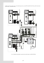
Fig. 8-25 Networking communication schematic of main unit and auxiliary unit for
KEM-75 DRS5 KH
8.4.14 Wiring instances
If multiple units are connected in cascade, the unit address should be set on the DIP switch ENC1. With 0-F being valid, 0 indicates
the master unit and 1-F indicate slave units.
L1
L2
L3
N
T
he l
en
gt
h o
f w
ir
e
sh
ou
ld b
e s
ho
rt
er
th
an 5
00
m
N
ot
es
Th
e w
iri
ng d
ia
gr
am
o
f a
ux
ili
ar
y
he
at
er
s
is
ju
st
fo
rr
ef
er
en
ce
,p
le
as
e
fo
llo
w
th
e
in
st
ru
ct
io
ns
of
co
rr
es
po
nd
in
g
au
xi
lia
ry
he
at
er
pr
od
uc
ts
.
P
le
as
e
ch
oo
se
s
uc
h
a
cc
es
so
ry
a
s
po
w
er
w
ire
,
sw
itc
h
of
au
xi
lia
ry
he
at
er
ac
co
rd
in
g
to
th
e
ac
tu
al
pa
ra
m
et
er
of
pr
od
uc
ts
an
d
na
tio
na
l
Contactor
Contactor
Power Transformer OUTPUT:8.5 V
~
Contactor
MAIN CONTROL
WIRECONTROLLER
X
Y
X
Y
X
Y
XT3
L1 L
2 L3
POWER 380-415V 3N~50Hz
ENC1
AC1
AC2
MAIN CONTROL
WIRECONTROLLER
X
Y
E
RD
YE
BK
BR
WH
POWER 380-415V 3N~50Hz
R
VV
-300/500 5X16mm
2
X
Y
E
AC1
AC2
RD
YE
BK
BR
WH
Main board
Slave board
CN22
CN46
CN1
19
CN123
HEA
T1
HEA
T2
PUMP
1
2
0
Ω
POWER 380-415V 3N~50Hz
R
VV
-300/500 5X16mm
2
26
XT3
L1 L
2 L3
ENC1
X
Y
E
RD
YE
BK
BR
WH
X
Y
E
AC1
AC2
RD
YE
BK
BR
WH
Main board
Slave board
CN22
CN46
CN1
19
CN123
XT3
L1 L
2 L3
ENC1
X
Y
E
RD
YE
BK
BR
WH
X
Y
E
AC1
AC2
RD
YE
BK
BR
WH
Main board
Slave board
CN22
CN46
CN1
19
CN123
POWER 380-415V 3N~50Hz
R
VV
-300/500 5X16mm
2
SLA
VE
SLA
VE
MONITOR
WIRECONTROLLER
MONITOR
WIRECONTROLLER
HEA
T1
HEA
T2
PUMP
HEA
T1
HEA
T2
PUMP


