

LINK
net
™
!
USER MANUAL
DCM000000008
Printed: 00.03.22,09:08
Revision Date:3/22/00
17
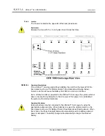
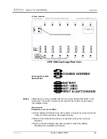
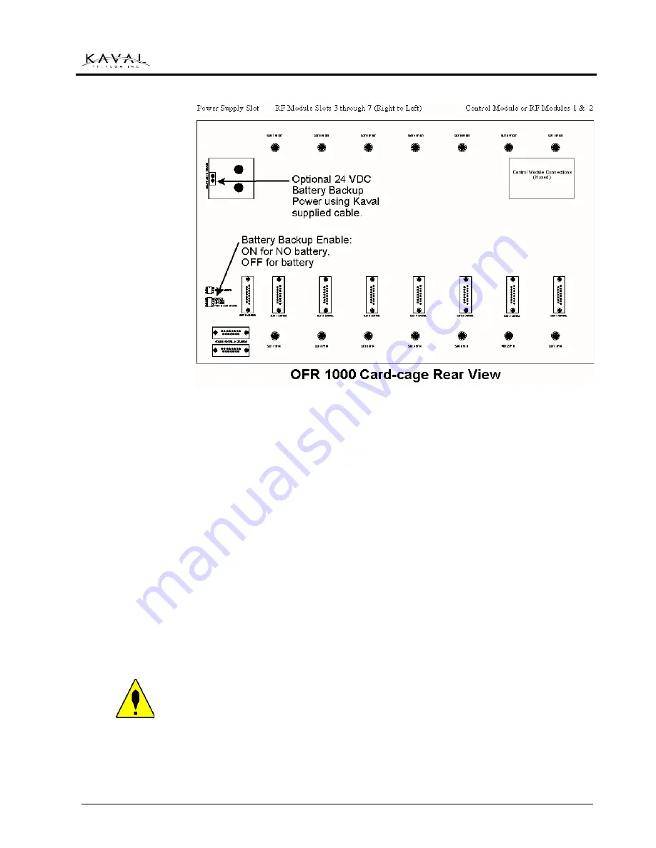
Battery connection
Installing the software
Each RF module has a number of built in changeable parameters that may be
changed in the field directly by using the optional Controller Module. If the Controller
Module is not used, then these parameters may be changed by running custom
software on an external PC running Windows 95/98/NT, connected through the
CONTROL PORT CONNECTOR
for each module, on the rear of the LINK
net
™
card-cage. The software will be shipped on a disk, (optionally, it may be delivered
electronically over the internet), with its own install program.
From the Windows
START
button’s
RUN
Menu, Use the
BROWSE
button to find
the
SETUP
program on the disk, and follow the on screen instructions. When set-up
is complete, there will be a KAVAL TELECOM INC. icon on the desktop.
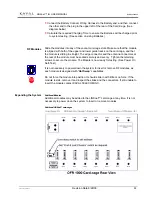
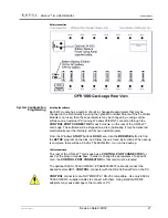
Cable connections
The rear of the LINK
net
™ card-cage has a
CONTROL PORT CONNECTOR
for
each of the plug-in module bays. In order to change the parameters of a specific
card, the
CONTROL PORT CONNECTOR
for that card must be located.
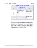
The optional KAVAL TELECOM INC. # CAB000000057 cable will connect the
desired female DB15
CONTROL
connector with the RS-232 Serial Port on the PC.
CONTROL
connectors are
NOT
DIRECTLY
RS-232 compatible. Use only KAVAL
TELECOM INC. supplied cables to connect with them. Using standard RS232
adapters may cause damage to the module or PC.
System Configuration
Programming


