background image

936.2079/A/

0206

/2.8e

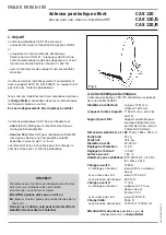
3. Before you…

begin to install, connect or utilise the parabolic antenna,
observe the information you find in these mounting
instructions. If you fail to pay attention to the information,
one cannot exclude


that due to wrong installation and connecting, or be-
cause of having modified components or using other
components, the antenna or the mounting place will
be damaged.


that because of inappropriate behaviour, risks for your
and other people's health and life will be created.


that the manufacturer will decline the liability for faulty
function and resulted damages.

It is most important that you are aware of the
responsibility you have for your own and other people's
safety when working on the antenna system!

Retain these instructions for possible later use
when questions come up. In case you sell the antenna,
pass the instructions on to the new owner.

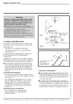
Attention!

Never install the antenna below overhead power lines.
It can be that the required safety distance is not kept.
Furthermore, make sure that the lateral distance to all
other electrical systems is at least 1 m.

Danger to life exists if you or the antenna make
contact with live parts!

Do not install the antenna on buildings with easily
inflammable roofs (straw, reed or similar material).

This is a fire hazard since the antenna is subject to
static charge and lightning.

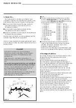
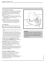
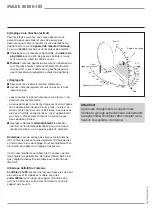
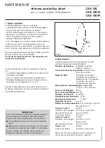
Fig. 2


For good reception the antenna must have an unob-
structed "visibility" to the south (+/-20). The horizontal
elevation angle must be 30°. The reception of the fol-
lowing satellites will then be possible:

1 TÜRKSAT 

Position 

42° East

2 ASTRA 2

Position 

28.2° East

3 ASTRA 3

Position

23.5° East

4 ASTRA 1

Position

19.2° East

5 EUTELSAT W2

Position

16° East

6 EUTELSAT HOTBIRD

Position

13° East

7 EUTELSAT W1

Position

10° East

8 EUTELSAT W3

Position

7° East

9 Thor 

Position

1° West

10Telecom

Position

5° West

11 HISPA-Sat

Position

30° West


Unobstructed "visibility" means that there must be no
obstacles (such as trees, buildings, roofs, balconies or
similar obstacles) between the antenna and the
satellite.
Obstacles of this kind can impair the reception or even
make reception impossible.

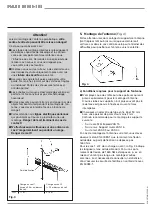
4. Mounting site

The selection of the right mounting site for your antenna
is important in order to ensure safe and satisfactory
operation. 
When choosing the mounting site, pay attention to
typical characteristics of the building. If the antenna is
installed on the edge of a roof or building, one must
reckon acc. to DIN 1055, Part 4 or 4131 with a higher
wind or oscillation load. This means that the dynamic
characteristics of the antenna and the building can
influence each other and change the characteristics
negatively. Disregard of these circumstances can lead to
exceeding the max. load or dynamic strength mentioned
in sect. 2.
It is not essential to mount the parabolic antenna on the
roof since it is not height above ground that matters but
an unimpeded line-of-sight to the satellite. Thus a
suitable mounting location may be found in the garden,
on the balcony/terrace or on a facade or garage, for
example.
Thus, if at all possible, the roof should be avoided as a
mounting location. In any event this reduces the amount
of work and avoids the dangers of doing installation
work on the roof!

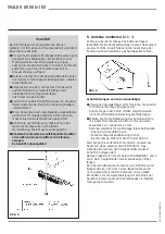
Fig. 2

South

East

West

Содержание CAS 120

Страница 1: ...zum Lieferumfang der Parabolantenne Achtung Verwenden Sie die Parabolantenne nicht zu anderen Zwecken als in dieser Anleitung angegeben Insbesondere d rfen Sie niemals irgendwelche Bauteile ver ndern...

Страница 2: ...Auswahl 1 T RKSAT Position 42 Ost 2 ASTRA 2 Position 28 2 Ost 3 ASTRA 3 Position 23 5 Ost 4 ASTRA 1 Position 19 2 Ost 5 EUTELSAT W2 Position 16 Ost 6 EUTELSAT HOTBIRD Position 13 Ost 7 EUTELSAT W1 Po...

Страница 3: ...n anlagen Es besteht Lebensgefahr 5 Antenne montieren Abb 4 Achten Sie bei der Montage des Antennentr gers Standfu Mast oder Wandausleger darauf dass dieser senkrecht steht Andernfalls kann die Ausric...

Страница 4: ...rauben 936 2079 A 0206 4 8d c Antenne vorbereiten Abb 6 1 Die vier Schrauben aus den Sicherungsholzleisten herausdrehen Entfernen Sie f r die weiteren Montageschritte die Kartonh lle noch nicht Sie di...

Страница 5: ...eme Multifeed bei 6 Satellitenabstand Bei Belegung der Positionen 1 und 5 kann auch zus tzlich mittig auf Position 3 ein Speisesystem montiert werden 3 Satelliten mit jeweils 3 Abstand Abb 8 Beispiel...

Страница 6: ...ystem Stellen Sie diesen Winkel an der Skala 10 bis 50 ein Dabei muss der entsprechende Skalenstrich auf der Halterung mit der Kante C des Reflektorhaltebleches fluchten Ziehen Sie die Schrauben A lei...

Страница 7: ...ls an die Grenze kommen wo die ersten sogenannten Fischchen Spikes am Bildschirm erscheinen Stellen Sie die Antenne dann in die Mitte zwischen diesen beiden Grenzpunkten Korrigieren Sie nun abwechseln...

Страница 8: ...t mit der Geb ude erdung a Geeignet als Erdungsleiter ist ein Einzelmassivdraht mit einem Querschnitt von min 16 mm2 Kupfer min 25 mm2 Aluminium oder min 50 mm2 Stahl oder metallische Hausinstallation...

Страница 9: ...delivery of the antenna Attention Do not use the parabolic antenna for purposes other than mentioned in these instructions Never modify any antenna parts or use different components than those specifi...

Страница 10: ...satellites will then be possible 1 T RKSAT Position 42 East 2 ASTRA 2 Position 28 2 East 3 ASTRA 3 Position 23 5 East 4 ASTRA 1 Position 19 2 East 5 EUTELSAT W2 Position 16 East 6 EUTELSAT HOTBIRD Pos...

Страница 11: ...the alignment of the antenna to the satellite can create problems a Requirements for the antenna support Only use masts or supports specially suited to be used as an antenna support Other supports of...

Страница 12: ...2079 A 0206 4 8e c Preparing the antenna Fig 6 1 Remove the four screws from the protective strip of wood For the following mounting steps do not remove the carton yet It protects the feed system supp...

Страница 13: ...systems allowing signal reception from satellites 6 apart When using positions 1 and 5 a feed system can also be additionally mounted in the middle on position 3 3 satellites 3 apart Fig 8 Example fo...

Страница 14: ...t this angle on the scale 10 to 50 Here the respective scale line on the support must be aligned with the edge C of the reflector support sheet Lightly screw on the screws A 5 Setting polarisation ang...

Страница 15: ...tly up and down until you see the first spikes on the screen of your TV set The best picture quality will be found in the middle of these boundary positions Now alternately correct the direction Azimu...

Страница 16: ...g conductor system is available a Suitable as grounding conductor a single solid wire with a min cross section of at least 16 mm2 for copper 25 mm2 for aluminium or 50 mm2 for steel or metallic domest...

Страница 17: ...ntenne parabolique Attention N employez pas l antenne parabolique pour d autres buts que ceux indiqu s dans cette notice En particulier vous ne devez jamais modifier quelque pi ce que ce soit ou emplo...

Страница 18: ...ion 28 2 Est 3 ASTRA 3 Position 23 5 Est 4 ASTRA 1 Position 19 2 Est 5 EUTELSAT W2 Position 16 Est 6 EUTELSAT HOTBIRD Position 13 Est 7 EUTELSAT W1 Position 10 Est 8 EUTELSAT W3 Position 7 Est 9 Thor...

Страница 19: ...Danger de mort 5 Montage de l antenne Fig 4 Faites attention lors du montage du support de l antenne m t tr pied m t ou bras mural que ce dernier soit vertical car dans le cas contraire cela peut entr...

Страница 20: ...ne Fig 6 1 D vissez les quatre vis des baguettes bois de s curit N enlevez pas encore l enveloppe de carton au cours des tapes de montage suivre L enveloppe sert de protection pour le support de la t...

Страница 21: ...deux t tes SHF un cart de 6 des satellites concern s L quipement des postions 1 et 5 permet de monter aussi une t te SHF sur la mi position 3 3 satellites d un cart de 3 chacun Fig 8 Exemple de la pos...

Страница 22: ...SHF Ajustez cet angle l chelle gradu e 10 50 Veillez ce que la divisi on correspondante de l chelle s aligne avec le bord C du support du r flecteur Serrez l g rement les vis A 5 R glage de la polaris...

Страница 23: ...aut puis vers le bas jusqu ce que vous arriviez la limite o les premiers clics apparaissent sur l cran Placez alors l antenne au milieu de ces deux positions limites Corrigez maintenant alternativemen...

Страница 24: ...nt tre reli s au plus court verticalement l installation parafoudre du b timent via un c ble de terre appropri s il n y a pas de protection parafoudre avec la terre du b timent a C ble de terre approp...

Страница 25: ...antenna parabolica per scopi diversi da quelli descritti nelle presenti istruzioni per l uso In particolare si raccomanda di non modificare mai alcuni componenti costruttivi oppure utilizzare altri c...

Страница 26: ...o scegliere i satelliti seguenti 1 T RKSAT Posizione 42 est 2 ASTRA 2 Posizione 28 2 est 3 ASTRA 3 Posizione 23 5 est 4 ASTRA 1 Posizione 19 2 est 5 EUTELSAT W2 Posizione 16 est 6 EUTELSAT HOTBIRD Pos...

Страница 27: ...namento di un temporale Persiste un imminente pericolo di morte 5 Montaggio dell antenna fig 4 Al montaggio del sostegno piede base traliccio oppure braccio a parete dell antenna si raccomanda di acce...

Страница 28: ...6 1 Svitare le quattro viti dal listelli di sicurezza Non rimuovere ancora l involucro di cartone per l ulteriore operazione di montaggio Questi serve per proteggere il sostegno del sistema di aliment...

Страница 29: ...la posizione di montaggio per due sistemi d alimentazione Multifeed ad una distanza dei satelliti di 6 Nell occupazione delle posizioni 1 e 5 il montaggio di un sistema di alimentazione pu essere eff...

Страница 30: ...vo trattino della scala inciso sul sostegno deve essere allineato con il bordo C della lamiera del riflettore Stringere leggermente le viti A 6 Pre regolazione della polarizzazione fig 9 Un sistema di...

Страница 31: ...mo Posizionare successivamente l antenna al centro tra questi due punti limite Correggere solo alternativamente la direzione Azimut e l inclinazione elevazione finch non migliora pi ulteriormente il r...

Страница 32: ...one contro colpi di fulmine con collegamento alla terra dell edificio a Come conduttori di terra sono particolarmente indicati un cavo massiccio singolo avente una sezione di min 16 mm2 di rame min 25...

Отзывы: