30
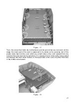
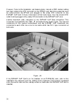
In order to replace the card back into the cabinet, the procedure described above
should be reversed. The most important point here is to make sure that the screw and
the grounding metal have been actually attached after the plastic clicks have been
fixed. At this stage, one is supposed to be sure that the grounding metal and the
ground distribution point are in contact. For that purpose, it may be measured whether
those two points are in short circuit or not.
Figure – 19
SPS48 POWER SUPPLY MODULE
The SPS48 Power Supply Module comes as attached below the plastic inner cover
that covers the RNT48 and PWT48 transformers inside the system cabinet, together
with cables connecting it to the power card.
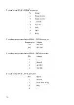
The SPS48 card is connected to the MB48IP
Motherboard through a 7-pin flat cable.
Moreover, the 3-pin connector, which is at the end of the cable that comes from the
PWT48 Power Transformer, and the 4-pin connector, which is at the end of the cable
that comes from the RNT48 Ringer Transformer are connected to the corresponding
connectors of the SPS48 card.
Output of the RNT48 Ringer Transformer is directly transferred to the MB48IP
Motherboard. Therefore, the 2-pin connector, which is at the end of the cable coming
from RNT48, is attached to the corresponding connector on the MB48IP.
Содержание MS48IP
Страница 1: ...www karel com tr TECHNICAL REFERENCE AND INSTALLATION GUIDE 09 2010 TELEPHONE EXCHANGE...
Страница 2: ...MS48IP TECHNICAL REFERENCE AND INSTALLATION GUIDE September 2010...
Страница 3: ......
Страница 15: ...7 The functional block layout of the cards is shown below Figure 6...
Страница 18: ...10 Figure 9 The dimensions of the EXP48 2 6 are 14 5 cm x 16 5 cm and it weighs 0 3 kg...
Страница 56: ...www karel com tr TECHNICAL REFERENCE AND INSTALLATION GUIDE 09 2010 TELEPHONE EXCHANGE...

