BR/BD 75/140 R, BR/BD 90/140 R
Troubleshooting
Page 63 / 71
New Unit Information 03.2004
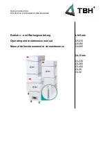
Drive sensor
1
Floor panel
2
Drive sensor (B1)
3
Unit housing
4
Adjusting screws (2x), drive sensor
Adjust drive sensor (B1)
– Remove the retaining screws of the floor panel
(1) and lift up the floor panel.
– Switch on the unit in test mode.
– Use the memo button to page through the dis-
play until “accelerator x.xV” appears. The in-
strument panel can be unscrewed and tilted to
the side to enable it to be read while adjusting
the sensor.
– Loosen the adjusting screws (4) and adjust
the drive sensor (2) by rotating it until the no-
minal value appears in the display.
– Retighten the retaining screws (4).
Nominal value:
Neutral voltage = 0.3V ± 0.05V
Note:
When installing the floor panel (1) ensure
that the wires are not clamped or pinded to
the drive sensor.
4
3
2
1
REVISED