background image

 13 

1

1

1

1

1

1

1

1

0

0

0

0

0

0

0

0

0

0

0

0

0

0

0

0


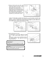
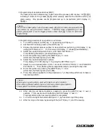
2.  Needle position sensor 

Disassemble the upper base cover (S) after loosing 4 pcs. of the screw (U). 
When the needle is positioned at the end of left side and also at the bottom dead point, 
adjust the clearance at 2mm between the looper shaft (W) and the proximity sensor 
(V), by adjusting the screw (X).    During this adjustment, confirm the turning on the 
lamp (Z) of the proximity sensor (V).    The up-down position of the proximity sensor 
(V) should be aligned to the center of the looper shaft (W), by adjusting the screw (Y). 


10

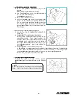
CLEANING THE MACHINE   


At the end of each day, remove the presser foot 
and the needle plate and then clean the slots 
of the needle plate and the area around the 
feed dogs. 


Содержание MAC100

Страница 1: ...INSTRUCTION INSTRUCTION INSTRUCTION INSTRUCTION Industrial Industrial Industrial Industrial Sewing Sewing Sewing Sewing Machines Machines Machines Machines First published March 2003 No 030043 ...

Страница 2: ... and maintenance procedures on this machine 2 Before starting the machine check to make sure the pulley cover safety cover etc are secured 3 Before adjusting cleaning threading the machine or replacing the needle be sure to turn off the power 4 Never start the machine with no oil in the reservoir 5 Refer to the parts list as well as this instruction manual before performing preventive maintenance ...

Страница 3: ...to back relationship 8 5 7 Looper setting distance 8 5 8 Adjusting the looper back spring 8 6 ADJUSTING OF NEEDLE GUARD 9 7 ADJUSTING THE PRESSER FOOT 7 1 Presser foot pressure 9 7 2 Position of the presser foot and foot lift 9 8 ADJUSTING THE STITCH FORMATION 8 1 Adjusting the looper thread eyelets 10 8 2 Position of the looper thread take up 10 8 3 Adjusting the needle thread guard 10 9 ADJUSTIN...

Страница 4: ...check the needle carefully to see that the scarf is turned to the rear of the machine see the illustration 1 1 1 1 3 To thread the machine 3 To thread the machine 3 To thread the machine 3 To thread the machine Thread the machine correctly by referring to the illustration below Incorrect threading may cause skip stitching thread breakage and or uneven stitch formation Furthermore set the thread ey...

Страница 5: ...urs of operation approx 1 month Then run the machine at the standard speed The machine pulley turns counterclockwise as seen from the end of the machine pulley see the illustration 2 2 2 2 2 Motor belt 2 Motor belt 2 Motor belt 2 Motor belt Motor 3 phase 2 pole 400W clutch motor Belt M type V belt Select the proper motor pulley according to the machine speed refer to the motor pulley outer diamete...

Страница 6: ...ing the oil and the filter element 3 Replacing the oil and the filter element 3 Replacing the oil and the filter element 3 Replacing the oil and the filter element To extend machine life be sure to replace the oil after the first 250 hours of operation To replace the oil follow the procedures below 1 Remove the V belt from the motor pulley and then remove the machine from the table 2 Remove screw ...

Страница 7: ... A A A A A AC C C C C C C C1 1 1 1 1 1 1 10 0 0 0 0 0 0 00 0 0 0 0 0 0 0 4 SEWING MACHINE INSTALLATION 4 4 4 4 1 Cutting the machine table 1 Cutting the machine table 1 Cutting the machine table 1 Cutting the machine table ...

Страница 8: ...ets Mount the machine head on the rubber cushions correctly 5 TIMING OF THE LOOPER TO THE NEEDLE 5 5 5 5 1 1 1 1 Nee Nee Nee Needle height dle height dle height dle height When the needle bar is at the top of its stroke needle position 2 3 there should be a distance of approximately 9 9 5mm from the top surface of the needle plate to the point of the needle Adjustment is made by loosening screws A...

Страница 9: ...dle plate Adjustment is made by loosening screw C The needle side stroke movement should start when the point of the needle moves up from the top surface of the needle plate The needle side stroke movement should stop when the point of the needle reaches the top surface of the needle plate This timing adjustment is made by worm gear D To adjust the position of the needle drop loosen screws A and t...

Страница 10: ...the needle at position 1 is 5mm move looper rocker D approximately 1mm to right After the adjustment is made tighten screws B and C securely Then tighten screw A with the collar fitted onto looper rocker D 5 5 5 5 5 Looper left 5 Looper left 5 Looper left 5 Looper left to to to to right movement right movement right movement right movement This adjustment should be made when the needle is at posit...

Страница 11: ...ooper setting distance 7 Looper setting distance 7 Looper setting distance Check the looper setting distance by referring to the table below If the looper setting distance is not correct perform 5 4 5 5 procedure again Needle position Setting distance mm 1 4 4 6 2 3 5 4 0 3 5 5 0 5 5 6 4 0 4 5 5 5 5 5 8 Adjusting the looper back spring 8 Adjusting the looper back spring 8 Adjusting the looper back...

Страница 12: ...nce at 0 0 05mm between the needle and the top of the looper At the same time check and adjust the position of the line a on the needle guard A which should be positioned at the top of the needle 7 ADJUSTING THE PRESSER FOOT 7 7 7 7 1 Presser foot pressure 1 Presser foot pressure 1 Presser foot pressure 1 Presser foot pressure The presser foot pressure should be as light as possible yet be suffici...

Страница 13: ...e by loosening screw D 8 8 8 8 2 Position of the looper thread take 2 Position of the looper thread take 2 Position of the looper thread take 2 Position of the looper thread take up up up up When the bottom of the needle s eye has reached the top surface of the needle plate while the needle is descending the looper thread taken up by looper thread take up E should be removed from the looper thread...

Страница 14: ... the bolt J and nut K 9 9 9 9 3 3 3 3 Adjusting of feed dog height Adjusting of feed dog height Adjusting of feed dog height Adjusting of feed dog height When the motor shaft lever is positioned at 9 1 The feed dog teeth C and D should be positioned at 0 5mm lower than the top surface of the needle plate Normally adjust the height by screw E and F The eccentric pin H should be used when the precis...

Страница 15: ... Lubrication Lubricate the oil in properly to the oil hole Z regularly after taking the rubber plug T out from the motor cover B 9 9 9 9 6 6 6 6 Position of sensor Position of sensor Position of sensor Position of sensor 1 Initial position sensor Refer to 9 1 Disassemble the motor cover B After loosing the screw E adjust the position at 1mm between the proximity sensor H and the detector G At this...

Страница 16: ...st the clearance at 2mm between the looper shaft W and the proximity sensor V by adjusting the screw X During this adjustment confirm the turning on the lamp Z of the proximity sensor V The up down position of the proximity sensor V should be aligned to the center of the looper shaft W by adjusting the screw Y 10 CLEANING THE MACHINE At the end of each day remove the presser foot and the needle pl...

Страница 17: ...g of control box 1 Mounting and wiring of control box Wiring of connectors Mount the control box A under the table in proper place by 4 pcs of the screw B Connect the following connectors to conformable pairs Parts Parts Parts Parts Description Description Description Description Proximity sensor C MOLEX 4 PIN Stepping motor D MOLEX 6 PIN Proximity sensor E MOLEX 3 PIN Panel board F OMRON 26 PIN P...

Страница 18: ... connect to the terminal 1 2 4 on the upper row of the relay socket C In case of single phase motor connect to the terminal 1 2 on the upper row of the relay socket C Make sure to connect the earth cord green or green yellow color to F together with the earth cord of the electric cord D Wiring of the electric cord D The following fig is the wiring method of 3 phase cord In case of single phase con...

Страница 19: ... cover A 2 Adjusting of the needle upper dead point Firstly move to keep the needle position at the upper dead point Then move to adjust the detector disc of the upper dead point C inner disc black color until turning on the lamp of the upper dead point refer to 11 4 fig 11 on the operation panel After that fasten the screw B 3 Adjusting of the needle bottom dead point Move to keep the needle posi...

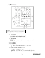
Страница 20: ...ion LED PROCESS Display the present setting process LED PATTERN Display a certain stitch number from the whole decorative stitches numbers within process SETTING SETTING To be used to set the numerical value of and AUTOMATIC OPERATION KEY AUTO To be used to start the sewing When turning off the lamp it is impossible to start the sewing Note Flower pattern No 4 is not available on MAC 100 yet ...

Страница 21: ...ramming of the pattern FLOWER PATTERN KEY FLOWER To be used to program the pattern But it is impossible to enter twice of the flower pattern continuously without feed pattern FEED PATERN KEY FEED To be used to program the pattern Please note that PATTERN 01 in the PROCESS is always set FEED PATTERN UPPER DEAD POINT LAMP When the needle is positioned at the upper dead point the lamp turns on BOTTOM...

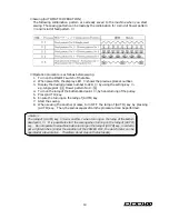
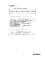
Страница 22: ... key e g Single picot 01 Flower pattern No 3 04 4 Turn on the lamp of the bottom dead point by hand turning of the pulley 5 Press AUTO key 6 Ensure the turning on the lamp of AUTO key 7 Start the sewing 8 When sewing the another process turn OFF the lamp of AUTO key by pressing AUTO key Then the same sequence from the procedure 3 can be performed Note The lamp of AUTO key turns on ONLY when turnin...

Страница 23: ...ing the SETTING key 7 Select the one desired pattern from 7 kinds of FEED PATTERN and FLOWER PATTERN Then flashing the correspondent lamp by pressing the key once 8 Enter this pattern by pressing the WRITE key once After that the flashing lamp turns ON 9 Then the same sequence from the procedure 6 7 8 should be performed to make a new sewing pattern 10 After entering all desired patterns keeping t...

Страница 24: ...shing lamp turns ON 6 Display 02 to LED display by using the SETTING key 7 Repeat the procedure 4 and 5 8 Display 03 to LED display by using the SETTING key 9 Repeat the procedure 4 and 5 10 Display 04 to LED display by using the SETTING key 11 Ensure the flashing of the lamp by pressing No 2 of flower pattern key once 12 Enter this pattern by pressing the WRITE key once After that the flashing la...

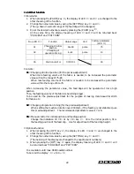
Страница 25: ...d to be decreased the parameter value within the range of 60 75 When increasing the parameter value the feed dogs will be operated at more high position Then the feeding volume of the fabric is becoming bigger To be used for the precise adjustment for the purpose of making more beautiful stitch formation etc 02 02 02 02 Changing of operation timing for the precise adjustment When setting the machi...

Отзывы: