17
NC
series
【
9
】
PRESSER FOOT
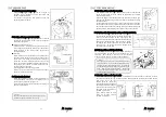
9-1 Adjusting presser foot pressure
The presser foot pressure should be as light as
possible, yet be sufficient to feed the fabric and
produce uniform stitches.
To increase the presser foot pressure, turn the
adjusting knob clockwise.
9-2 Position of the presser foot & foot lift
Fit the presser foot onto the presser bar so that the
needle can drop correctly to the center of the presser
foot needle drop hole.
■
Position of the presser foot
Loosen screw A. Adjust by moving the presser foot
left or right while checking to make sure the needle
drops correctly to the center of the presser foot
needle drop hole.
■
Foot lift
For machines with the spreader, the presser foot
should be 6mm above the top surface of the needle
plate. Check to make sure presser foot does not
touch the spreader with the presser foot in the
above position. For machines without the spreader,
the presser foot should be 8mm above the top
surface of the needle plate.
Set stopper B at the required position.
Fasten the presser foot lift lever with nut C so that
the lever cannot be lowered.
9-3 Adjusting the float-foot
When the adjusting screw D is turned clockwise or
counterclockwise, the presser bar lifting lever is
pressed down to lift the presser foot.
Adjusting the height of the float-foot according to
the sewing condition.
< Note >
In case of the float-foot is not used, use the sewing
machine with the screw E moves to top.
18
NC
series
【
10
】
STITCH FORMATION
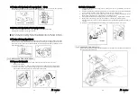
10-1 Position of the needle thread guides
The distance from the center of the eyelet of the needle thread
guide to that of the set screw should be approximately 17.5mm
(see the illustration).
Adjust the height of the thread guides by loosening screws A and
moving each thread guide up or down (refer to the mark shown in
the illustration).
If the stitch formation cannot be changed extremely by adjusting
the height of the thread guides because of the thread to be used,
unravel the thread after test sewing and adjust the height of the
thread guides while checking the tension of the needle thread.
10-2 Position of the thread guide on the needle thread take-up
When the needle bar is at the bottom of its stroke,
needle thread take-up bracket A should be level and
refer to the mark shown in the right figure the
position of the thread guide of needle thread take-up
B. To make this adjustment, loosen screws C and D.
To tighten the needle thread, move needle thread
take-up to Y. To loosen the needle thread, move
needle thread take-up to X.
10-3 Timing of the needle thread take-up
The timing of the needle thread take-up in relation to
the up-and-down movement of the needles can be
adjusted. This timing is factory-set to synchronize
with the up-and-down movement of the needle bar.
10-4 Position of the needle thread guide
When the needle bar is at the bottom of its stroke, the center of the needle bar eyelet A
should be level with the top surface of needle thread guide B. To make the needle thread
loop large, move up the
thread guide B, for more
stretchable threads. To make
the needle thread loop small,
move down the thread guide
B, loosen screw C and move
guide B up or down.
Also, loosen screw E and
move up or down thread
guide D as required.
< Note >
The rod ball is factory-set at 5.5mm from the rear
end of the shaft. To make the needle thread loop
small, move the rod ball to the front. To make the
needle thread loop large, move the rod ball to the
back. Remove the rubber top plug. Loosen the
screw of (A) with a 5mm wrench. Then move the
rod ball to the front or back.
Содержание NC Series
Страница 2: ......
Страница 3: ......
Страница 4: ......
Страница 5: ......
Страница 6: ......
Страница 7: ......
Страница 8: ......
Страница 9: ......
Страница 10: ......
Страница 11: ......
Страница 12: ......
Страница 13: ......
Страница 14: ......
Страница 15: ......
Страница 16: ......
Страница 17: ......
Страница 18: ......
Страница 19: ......
Страница 20: ......
Страница 21: ......
Страница 22: ......
Страница 23: ......
Страница 24: ......
Страница 25: ......
Страница 26: ......
Страница 27: ......
Страница 28: ......
Страница 29: ......
Страница 30: ......
Страница 31: ......
Страница 32: ......
Страница 33: ......
Страница 34: ......
Страница 35: ......
Страница 36: ......
Страница 37: ......
Страница 38: ......
Страница 39: ......
Страница 40: ......
Страница 41: ......
Страница 42: ......
Страница 43: ......
Страница 44: ......
Страница 45: ......
Страница 46: ......
Страница 47: ......
Страница 48: ......
Страница 51: ...NC Series Instruction Manual NC1103 4 G series ...
Страница 63: ...NC J SJ Series Instruction Manual NC1001GSJ NC1001GSJF NC1001GJ ...


