18
Service and Repair Manual
Model 1400KV/1400BV
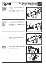
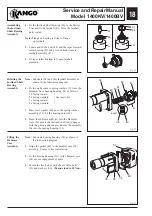
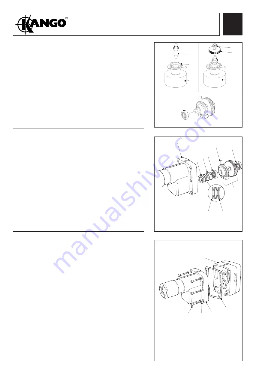
Fig. 33
Fig. 31
Fig. 32
INSERT A
Assembling
the Inclined
Shaft Bearing
Assembly
1.
Fit the Inclined Shaft Bearing (46) to the Service
Tool and fit the layshaft (47). Press the layshaft
until seated.
Note:
Flange on bearing is fitted to flange
on layshaft.
2.
Locate and fit the gear (48) and the taper forward
roller bearing (41) and press on both items to
layshaft assembly (47).
3.
Fit taper roller bearing (41) onto layshaft
assembly.
Refitting the
Inclined Shaft
Bearing
Assembly
Note:
Lubricate (34) and (46) layshaft assembly as
shown in the lubrication diagram.
1.
Fit the eight concave spring washers (39) into the
Hammer Case bearing housing (34) as follows:
2 x facing inward
}
2 x facing outward
}See insert (A)
2 x facing inward
}
2 x facing outward
}
2. Place steel washer (40) on to the spring washer
assembly (39). Fit the bearing outer (41).
3.
Insert the ISB assembly (A) into the Hammer
Case (34) ensure the inclined shaft (46) engages
with the piston gudgeon pin. Ensure the assembly
fits into the bearing housing (34).
A
46
47
A
41
41
A
41
34
39
40
41
46
48
Note:
Lubricate bearing housing (50) as shown in
the lubrication diagram.
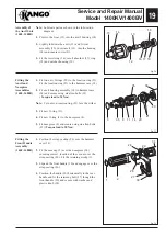
1.
Align the gasket (49) to the hammer case (50)
assembly. Ensure correct orientation.
2.
Fit the bearing housing (50) to the hammer case
(34) ensure engagement of gears.
3.
Secure the two halves with the six Allen bolts
(35) and washers (36).
(Torque load to 30 Nm).
Fitting the
Hammer
Case
Assembly
35
34
49
50
36
39
40
Содержание 1400 Series
Страница 1: ......


