16
Service and Repair Manual
Model 1400KV/1400BV
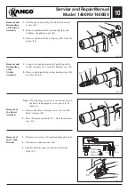
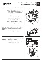
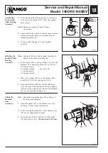
Fig. 22
Fig. 23
Fig. 24
Assembly of
the rear
handle
79
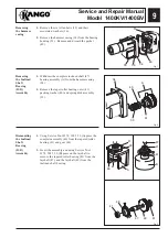
1.
Fit the lower handle support (79) and rubber into
the motor housing (73) and secure the lower
locking plate (80).
2.
Depress the switch (83) trigger and engage the
locking button. Fit the unit into the handle front.
(77) and depress the trigger, ensuring correct
location of the switch (83).
3.
Identify and connect the switch leads, POS (+) to
lower terminal and NEG (-) to upper.
4.
Fit the handle rear cover (81), ensure leads are
positioned correctly. Fit the handle into lower
support rubber and housing (79).
5.
Fit the upper support rubber (78) and handle
support (79) and locate into motor housing (73).
Fit and secure the upper locking plate (80).
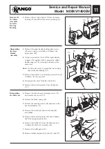
Refitting the
Motor Housing
Assembly
1.
Position the motor housing (73) over the bearing
housing (50) ensuring correct orientation.
2.
Fit the six inserts (74) and their respective Allen
bolts (35).
(Torque load to 15 Nm).
50
74
35
73
DETAIL A
DETAIL B
CONDENSOR
CONDENSOR
CONNECTION
SWITCH
CONNECTION
FIELD
CONNECTION
BLUE
DETAIL B
DETAIL A
SWITCH LEADS
SWITCH LEADS
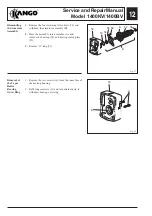
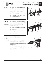
1.
Identify and connect cables to terminal block (87),
as shown in diagram opposite.
2.
Fit and secure the terminal block mounting plate
(86) ensuring correct location of the condensor
unit (89).
(Torque load to 0.8 Nm).
Mounting the
input termi-
nal block
89
87
86
76
69
73
79
80
81
83
77
80
78
82
69
Содержание 1400 Series
Страница 1: ......


