background image

9

KS-6001

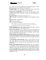
but in this case, the level and left VU meter indication (on the 

KS-342) will be lower than the actual values.

Channel fader 

Turn clockwise to increase, and counterclock-

wise to decrease, the output level of this channel.

Output bus assignment 

Use  this  to  send  the  output  of  the 

channel to the left (

L

), right (

R

) or center (

C

 – left and right) out-

put busses.

Input selector 

Use this to select between:

P48 

Condenser  microphones  requiring  +48V  phantom  power-

ing

Dy-M 

Dynamic  microphones

LINE 

Line-level sources

A-B

 - A-B type microphones

Ensure that only microphones corresponding to the selection 
are connected to the appropriate inputs, otherwise damage may 
occur to the KS-6001 and to the microphones.

PEAK indicator 

Shows when the pre-fader, post-gain signal is 

more than 28 dB above the optimum level.

Input trim control 

Used to adjust the level of the signal fed 

to each channel. The amount of trim depends on the input set-
ting: the blue figures indicate line-level settings, and the white 

figures indicate microphone levels.

Channel fader link switches (FD LINK)

 When these switches 

are on (in the right position), the even-numbered fader controls 
the levels of both its own channel and the odd-numbered chan-
nel to its left.

L & R master level controls

 Push to extend these controls 

and  push  again  to  recess  them.  These  affect  the  level  of  the 
signal  fed  from  the  unit  to  the  KS-342  through  the  MIX  OUT 
connector.

Power and status indicator 

This indicator serves two purpos-

es. Firstly, it acts as a power indicator, showing when power is 

supplied to the  unit. Secondly, the color of the indicator shows 
the current setting of the output bus as set by the side rotary 

control (

TO 342

). Green indicates the bus mix is active, yellow 

indicates AUX (for monitoring) and red indicates off, or a power 
supply below 9V.

Содержание KS-6001

Страница 1: ...POWER PEAK PEAK PEAK PEAK FD LINK FD LINK 0 0 2 L F P R L C 0 0 2 70 30 20 4 L F P R L C 0 0 2 L F P R L C 0 0 2 L F P R L C LINE Dy M P 48 A B 70 30 20 4 70 30 20 4 70 30 20 4 LINE Dy M P 48 A B LIN...

Страница 2: ......

Страница 3: ...ed under different conditions there is a risk of fire damage to the unit or personal injury Note the following with regard to external power supplies Make sure the polarity of the external powering de...

Страница 4: ...e are mistakes in the connections it is pos sible that either the KS 6001 or the other unit s will be dam aged In the event that smoke or odors come from the unit turn off the power and remove all bat...

Страница 5: ...ecessed again by sliding the release lever and pressing down the connector until it locks at the recessed posi tion Connector cover if the KS 6001 is being used as a stand alone unit you should always...

Страница 6: ...type of carrying case make sure that all units are firmly affixed in the appropriate specially designed carrying case In the event of a major shock to the unit there is a risk of damage to the connec...

Страница 7: ...e connectors supplied or approved by Kamesan in the event of any doubt please contact Kamesan or an appointed distributor directly Mix switch The three position switch is useful when using the KS 6001...

Страница 8: ...0 0 2 L F P R L C 0 0 2 L F P R L C LINE Dy M P 48 A B 70 30 20 4 70 30 20 4 70 30 20 4 LINE Dy M P 48 A B LINE Dy M P 48 A B LINE Dy M P 48 A B LCF PFL switch Use this control to sweep the low cut fi...

Страница 9: ...l Input trim control Used to adjust the level of the signal fed to each channel The amount of trim depends on the input set ting the blue figures indicate line level settings and the white figures ind...

Страница 10: ...There is a risk of serious dam age to equipment if the wrong selection is made Make the multi pin output power connection Turn on the power when the connections have been made The unity gain position...

Страница 11: ...40mA High pass filter 12dB octave sweepable cutoff between 20Hz and 200Hz Outputs Output level 20dBs from a 7 pin Cannon connector electrically balanced low impedance output Maximum output 8dBs into...

Страница 12: ...e KS 342 and KS 6001 used together 2 h manganese cells 3 h alkaline cells 6 h NP 1 pack Battery life KS KS 6001 used as standalone 2 h manganese cells 3 h alkaline cells 6 h NP 1 pack Physical specifi...

Страница 13: ...X BUS PFL TALLY PFL TALLY XLR7 32 L MIX BUS R MIX BUS POWER OUT INPUT INPUT INPUT INPUT EXT I O A B12V MONI OUT L AUX IN R AUX IN 9 16V 9 16V 20dBs XLR 3 XLR 3 XLR 3 XLR 3 EXT I O INS I O MIX OUT EXT...

Страница 14: ...y large heavy equipment ease of use since time is always of the es sence in the environments where our products are used and quality to match the needs that today s broadcasters require Our head offic...

Страница 15: ......

Страница 16: ...Sigma Systems Engineering Co Ltd 3 5 2 Okubo Shinjuku ku Tokyo 169 0072 JAPAN Tel 81 3 3204 2611 Fax 81 3 3204 2250 e mail sales kamesan co jp...

Отзывы: