7
KS-6001
Parts of the KS-6001
Since the operation of the KS-6001, once it has been fitted as
a sub-mixer, is a relatively simple matter, this section contains
the information you need to get up and running with the unit in
most cases. Later sections contain more detailed information
covering special circumstances.
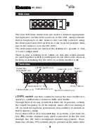
Side view
1.FG
7.0V
6.+10
7
6
5
4
3
2
1
CN Pin Assign
(-20dBs)
MIX OUT
5.Rch C
4.Rch H
3.Lch C
2.Lch H
BUS MIX
(MONI)
AUX
OFF
POWER
16V
~
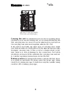
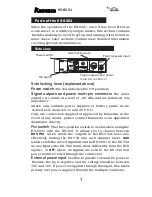
Side locking lever (explained above)
Power switch
(the dot indicates the ON position)
Signal outputs and power multi-pin connector
The mixer
outputs are made at a level of –20 dBs and are balanced low-
impedance.
Attach only suitable power supplies or battery packs as de-
scribed here (between 16 and 20 V DC).
Only use connectors supplied or approved by Kamesan. in the
event of any doubt, please contact Kamesan or an appointed
distributor directly.
Mix switch
The three-position switch is useful when using the
KS-6001 with the KS-342. It allows you to choose between
BUS MIX
: which sends the outputs to the KS-342’s buss mix,
effectively turning the KS-342 into an 8-channel mixer.
AUX
,
which sends the mixed signals from the KS-6001 to the KS-342
as aux inputs (the KS-342 treats these differently from the BUS
inputs); or
OFF,
where no signals are sent to the KS-342 (but
power is still received through the connector).
External power input
Use this to provide external DC power to
the unit—the tip is negative, and the voltage should be between
10 V and 16 V. If power is supplied through this input, this takes
priority over power supplied through the multipin connector.
Side locking lever
Signal outputs and power
multi-pin connecvor
Mix switch
External power input
Power switch


