


Installation and Operation Manual
Revision B
5-3
0150-0133
If no controllable devices (multiplexers) are found on the network, but does see another keypad or PC,
the display shows:
No units connected
, and the keyboard goes to the
Standing by ...
state.
When Polling Sees Nothing on the Network
When a keyboard poll finds no other devices attached to the network, it enters the telemetry mode,
which allows the keyboard to communicate directly to the dome cameras.
The top line of the display shows:
(where
(KB - 01)
is the keyboard address,
and
02
is the camera #.)
Telemetry
(KB - 01) 02
CAUTION:
If the keyboard is powered up at the same time as the multiplexers, for example,
because they are all powered from a central power controller, then the keyboard
may start polling before the multiplexers are fully powered up.
In this case, the keyboard may not detect all multiplexers, and so the operator
must manually poll the network once all devices are powered up.
(Refer to section 5.3, page 5-4 for the procedure to manually poll the network
from the CBR-KB3.)
Disconnecting From a Multiplexer
Disconnection by an Operator
The CBR-KB3 cannot be connected to more than one multiplexer at the same time. When an operator
has completed control actions on a specific multiplexer, before the CBR-KB3 can connect to a new
multiplexer, it must disconnect from the current
multiplexer.
To disconnect from a multiplexer, the CBR-KB3 must be in the
Connected ...
s
tate.
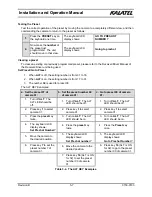
More Examples:
Suppose the user has been controlling multiplexer number 2 and now wants to disconnect. When the
connection is successfully broken, the sequence of keystrokes is the same as those for connecting to
a multiplexer.
1.
Press the
#
key once.
The display shows:
Enter a Target
Unit ID ...
2.
Press the
numeric
key - in this case
2
.
The display briefly shows:
Trying to
Disconnect…
This is quickly followed by:
Unit Disconnected!
The CBR-KB3 is now in the
Standing by ...
state.
If for some reason the connection cannot be broken (e.g., the multiplexer does not respond to the
CBR-KB3’s disconnect request), the keyboard remains in the
Connected ...
state. In this case, the
operator should retry again.
If, after a few tries, the keyboard is still in the
Connected ...
state, a manual re-polling of the
network should be done. (See Manual polling of the network in section 5.3 on page 5-4).
Automatic Disconnection by a Multiplexer
To prevent a multiplexer from remaining unavailable to other keyboards, the CBR-Plus 10/16/32
multiplexers disconnects from a controlling keyboard that has been idle for more than 30 minutes.
Содержание CBR-KB3
Страница 4: ...Installation and Operation Manual 0150 0133 iv Revision B This page intentionally left blank ...
Страница 6: ...Installation and Operation Manual 0150 0133 vi Revision B This page intentionally left blank ...
Страница 10: ...Installation and Operation Manual 0150 0133 1 4 Revision B This page intentionally left blank ...
Страница 12: ...Installation and Operation Manual 0150 0133 2 2 Revision B This page intentionally left blank ...
Страница 37: ...Installation and Operation Manual Revision B 7 3 0150 0133 ...


