


PK3520_09_07 • REMOTE ACCESS CONTROLLER - 660G XT
14
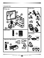
6.0 Annex A Wiring Diagram
Controller
Board
Battery
Status
Power Supply
126-511878
Battery
120-507947
DC Out
Battery
TOP LED
BO
TT
OM LED
XFMR
Power
Status
P
1
C
B
F
R
K
N
O
1
2
1
3
2
1
3
AC FAIL
124-511689-101
Low Bat
+
-
2
1
+
++
+
-
-
-
-
2
2
1
1 2 3
E
RED
BLK
Electromagnetic
Lock
504631
NC
C
REX (Pushbar)
Fire Alarm
Panel
(Contact OPENS
on fire alarm)
Not supplied
by Kaba
S
Bypass
Active
Reset
SW1
SW2
D46
D45
D41
D42
J1
J2
J3
J7
J8
J12
J13
J14
J15
J16
J17
J18
J19
D43
D44
SW3
ON
Keypad
(Ingress)
Tamper
Switch
Power Adaptor
For Europe / UK / Autralia 24 VDC
126-511939
For North America 24 VAC
062-511929
Unswitched AC
Power Source
1
2
3
4
5
Key Override
(Key switch not supplied
by Kaba)
D
Remote Unlock
T
Diode
12V
GND
1 2 3 1 2 3
1
2
3
1
2
3
1
2
3
1
2
1
2
3
4
1
2
3
4
1
2
3
4
1 2 3 1 2 3 4
1 2 3 4
(See *NOTE)
IMPORTANT: Read manual before
installation or maintenance
of the unit.
P
2
Keypad
(Egress)
Garage
Door
Opener
Remote Access Controller - 660G XT
*NOTE: Remove short from connector J18,
pins 3 and 4, if fire panel contact
remote interface is used
FRONT PANEL INDICATORS:
Green ON = Power Status OK
Green ON = Battery Status OK
Exit Device for Push Bar Pannex
120ASS-1 and L120ASS-1
(See Instruction Booklet)
040-506652
Motion Detector
(See Instruction Booklet)
RD
BLK
Electric
Strike
506381
Diode
Q