


PK3520_09_07 • REMOTE ACCESS CONTROLLER - 660G XT
11
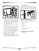
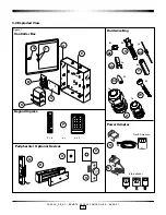
Mounting Keypad
IMPORTANT: The installation bag supplied with the
keypad includes screws for metal panel installation or
inserts and wood screws for drywall installation. Use
the relevant screws according to which surface the
keypad reader will be installed on.
!
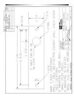
IMPORTANT: Refer to the drilling template in Annex C
to select the drill size of the mounting holes for the
keypad.
!
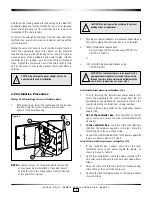
1.
To install the keypad reader (P) in the desired location,
use the template Annex B to mark the holes for the cable
and screws.
NOTE:
A dual reader installation has one Ingress (entry) (P1)
and one Egress (exit) keypad (P2).
2.
Wearing safety glasses, drill the holes in the wall
according to the diameters indicated in the drilling
template dependent on the type of surface the keypad is
installed on.
3.
For single reader installations:
connect the cable
from the keypad (P) to the terminal blocks on the
controller board (C) as per Annex A, Table 1.
For dual reader installations:
connect the Egress
keypad (P2) and the Ingress keypad (P1) to the terminal
blocks on the controller board (C) as per Annex A, Table 1.
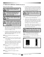
4. Caution with keypad selectable for 5 or 12 volts. A
jumper plug is installed on one of the pins. This is the
default setting for 12 volt operation. Incorrect voltage
selectable may cause damage. Refer to manufacturer’s
specification document provided with reader.
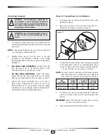
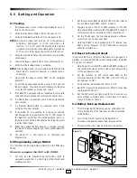
Step 8: Completing the installation
1. If the panel door was removed, reinstall the door on the
660G XT enclosure.
2. Bend the two tabs of the panel door with pliers to a
maxium of 30 degrees as shown in Figure 12.
Figure 12
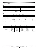
3. Connect the LED wire harness from the power supply (B)
to the panel door’s LEDs (F) as indicated below and in
Annex A, Table 6. The LEDs (F) have a polarity indicator,
‘+’, on the shaft that is to be used as a reference.
NOTE:
The wires must be connected with the proper polarity.
Once the terminals are installed they are designed to
have a tight fit so removal may damage the LED itself.
LED
Location
‘+’ terminal ‘-’ terminal
Description
on door
connection
connection
Power status
Top
Red
Orange
Battery status
Bottom
Red
Yellow
4. If a battery (K) is part of the system ordered connect the
red (+) and black (-) wires from the power supply to the
battery.
IMPORTANT:
Ensure that the proper connections are made
(ie: red to red, black to black).
5. Plug the power adaptor into the AC power source.