9
E. REVERSING THE OUTSIDE
LEVER FOR SERIES WITHOUT
MECHANICAL OVERRIDE
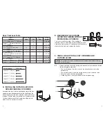
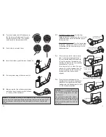
The lever is field reversible. If the handing is
incorrect, insert a small pick or flat screwdriver in the
hole in the hub as shown. Gently pry back the spring
clip inside the hub, and remove the handle.
F. INSTALLING OPTIONAL KEY OVERRIDE AND
OUTSIDE LEVER
Important: Assemble the lever, cylinder and lock components before affixing
the entire unit to the door.
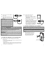
F-1
Upon unpacking, the lock housing with mechanical override should look
like the diagram below with:
• The small indents (i) on the cross of the override shaft (m) in line
horizontally
• The nylon washer (c) and the spring washer (d) on the drive tube
• The lever catch (f) in the out position
• Cylinder (j) and 2 keys (n) included in the hardware bag
(f)
(i)
(c, d)
(n)
(m)
(j)
8
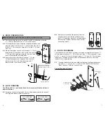
Door Thickness Table
Door
Spacer 02 Spacer 04 Spacer 05
Screw
Thickness
thin 125
328
length
1
3
⁄
8
"
(35 mm) up to 1
9
⁄
16
" (
40 mm)
-
1
-
3
⁄
8
"
(10 mm)
Over 1
9
⁄
16
"
(40 mm) to less than
1
11
⁄
16
"
(43 mm)
1
3
⁄
4
" (
44 mm) Door
1
11
⁄
16
" (
43 mm) to less than
1
2
-
5
⁄
8
" (
16 mm)
1
7
⁄
8
"
(48 mm)
1
7
⁄
8
"
(48 mm) to 1
15
⁄
16
"
(49 mm)
1
-
1
5
⁄
8
" (
16 mm)
2" (50 mm) Door
over 1
15
⁄
16
" (49 mm)
to less than
2
-
1
3
⁄
4
" (
19 mm)
2
1
⁄
8
" (
54 mm)
2
1
⁄
8
"
(54 mm) to 2
3
⁄
16
"
(56 mm)
-
1
1
3
⁄
4
" (
19 mm)
2
1
⁄
4
"
(57 mm) Door
over 2
3
⁄
16
"
(56 mm) to 2
3
⁄
8
"
(60 mm)
Over 2
3
⁄
8
"
(60 mm) to 2
1
⁄
2
"
(64 mm)
-
-
2
7
⁄
8
" (
22 mm)
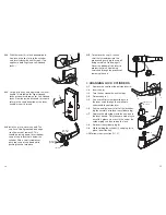
D. INSTALLING OUTSIDE LEVER ON
NON-MECHANICAL OVERRIDE
Assemble the lever on the outside housing in the hori-
zontal rest position appropriate to the handing of the
door. Simply push the lever onto the tube until it clicks
in place. If more force is required, use a rubber mallet.
Test the attachment of the handle by pulling on it to
make sure it is securely fastened.
Screw Length
Full Scale
Length
3
⁄
8
"
(10 mm)
Length
1
⁄
2
"
(13 mm)
Length
5
⁄
8
"
(16 mm)
Length
3
⁄
4
"
(19 mm)
Length
7
⁄
8
"
(22 mm)
-
2
-
1
⁄
2
" (
13 mm)
2
1
1
7
⁄
8
" (
22 mm)


