5
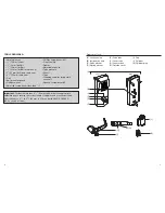
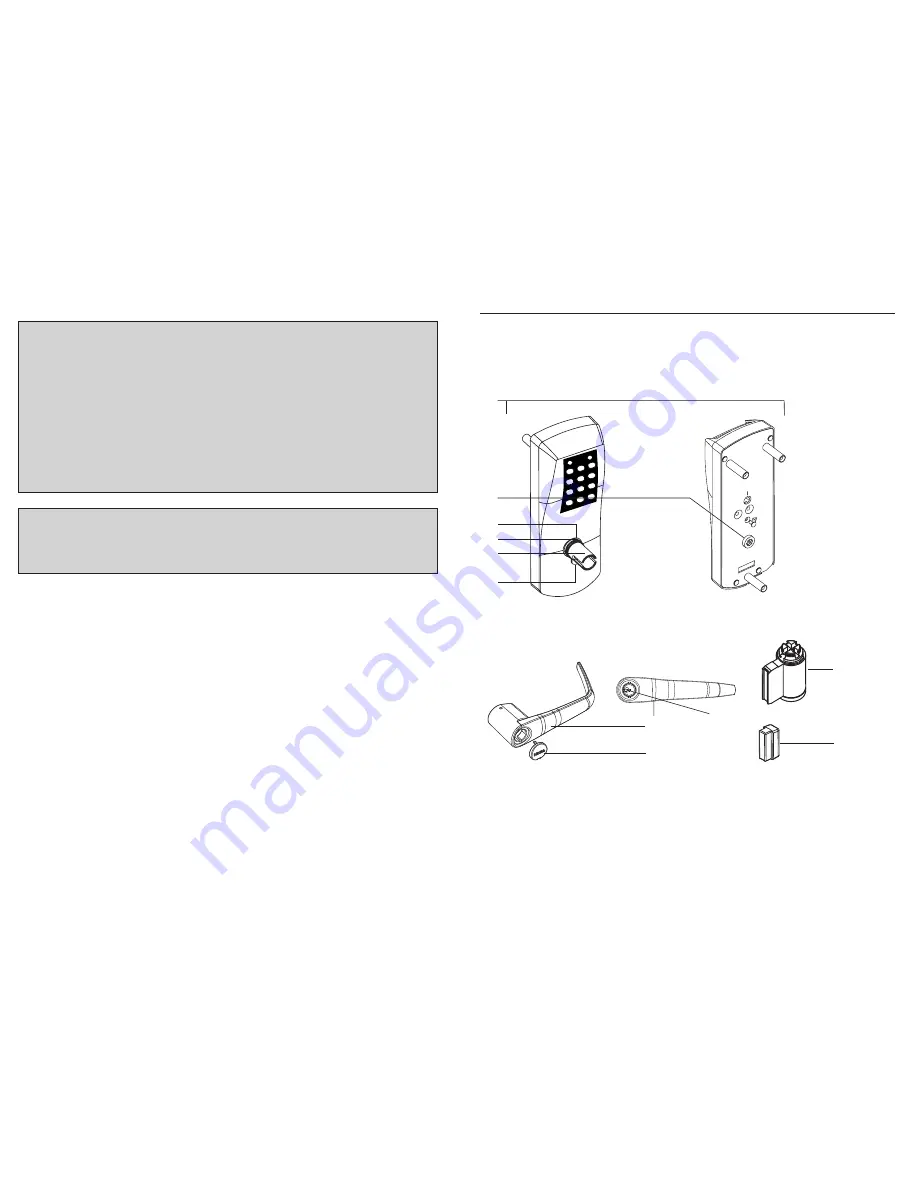
(A) Lock housing
(B) Inside drive hub
(C) Nylon washer
(D) Spring washer
(E) Drive tube
(F) Lever catch
(G) Countersink
(H) Outside Lever
(I) Cap
(J) Cylinder
(K) Cylinder plug
Diagram of lock:
Back
Front
(A)
(E)
(B)
(D)
(F)
(G)
(H)
(I)
(J)
(K)
(C)
4
TOOLS REQUIRED:
Important: For doors more than 2
1
⁄
2
" (64 mm) thick, order the appropriate
hardware bag to receive the correct length of spindles and mounting screws.
Door thickness > 2
1
⁄
2
" to 3
3
⁄
4
" (64 mm to 95 mm), part# 062-510189-XXX;
(XXX = choice of finish).
• Safety glasses
•
1
⁄
2
" (13 mm) chisel
•
1
⁄
8
" (3 mm) drill bit
•
1
⁄
2
" (13 mm) drill bit
•
7
⁄
8
" (22 mm) drill bit or hole saw
• 1" (25 mm) drill bit or hole saw
• 2
1
⁄
8
" (54 mm) hole saw
• Drill
• Awl or center punch
• Rubber mallet
• Small flat screwdriver (less than
1
⁄
8
")
• Phillips screwdriver (#2)
• Fine steel file
• Router
• Adjustable square
• Tape measure
• Pencil
• Tape
• Cleaning supplies (drop cloth,
vacuum)
• Spanner screwdriver #6


