background image

5

P

ART

 I: I

NSTALL

 F

RONT

 H

OUSING

 A

SSEMBLY

Install Instructions for Cencon Motorized Deadbolt Entry Assembly

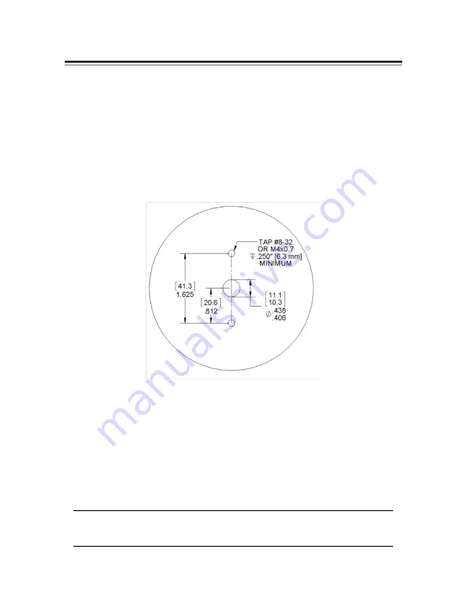
1.  Use the dimensions provided in Figure 2 to establish the exact locations 

(relative to the spindle hole) of the mounting holes for the Entry Device and the 

lock assembly. Be sure to consider the cable length from the entry device to the 

lock.

2.  The spindle hole diameter can be a minimum of .406” (10.3mm) to a maximum 

of .438” (11.1mm). The .406” (10.3mm) diameter is recommended. Spindle hole 

must be deburred.

3.  The Entry Device mounting screws require drilled and tapped holes to 3/8” 

(9.5mm) depth if possible (minimum 1/4” or 6.4mm depth required.) 


(Figure 2 – Hole Locations. Not to scale)

4.  Screw the two mounting studs into the stud mounting holes just drilled. Tighten 

to approximately 15-20 inch-pounds.

5.  Open the safe door and keep it open.

6.  Feed the assembly’s two cables through the spindle hole one at a time.  Note: 

maximum door thickness is 5 inches to allow for current cable length.

7.  Place the entry assembly onto the front of the safe door. Place the two larger 

holes of the entry assembly over the two mounting studs as shown in Figure 

2, and then apply downward pressure to pop the mounting studs onto the wall.  

Pull up slack in the cables from the inside of the safe door as you place the 

assembly so that the cables will not be damaged. The entry should now be held 
in place by the mounting studs.

NOTE: 

To remove the entry assembly, apply upward pressure to the entry unit until 

the entry studs are moved out of the way, and then rotate it laterally to the left to 
reveal the entry’s reverse side.

Содержание Cencon MDB 30N

Страница 1: ...03 USA Voice 919 381 4235 Fax 770 831 8598 Certification Exhibit FCC ID 2AHFM BTCENMDB IC 21164 BTCENMDB FCC Rule Part 15 247 IC Radio Standards Specification RSS 247 ACS Project Number 15 3053 Manufa...

Страница 2: ...CENCON Motorized Dead Bolt ATM Security Lock INSTALLATION INSTRUCTIONS PRELIMINARY 05 26 2016...

Страница 3: ...L FRONT HOUSING ASSEMBLY 6 PART II INSTALL LOCK CASE ASSEMBLY 8 PART III INTERCONNECT BOX INSTALLATION 8 BASIC LOCK OPERATIONS 10 OPENING IN SHELVED MODE 10 CHANGE THE SHELVED MODE COMBINATION 11 GEN2...

Страница 4: ...nd used in accordance with the instructions may cause harmful interference to radio communications However there is no guarantee that interference will not occur in a particular installation If this e...

Страница 5: ...doors of any material NOTE As is the case with all mechanical and electronic locking devices the container and boltworks must be designed to protect the lock PREPARE FOR NEW INSTALLATION OF THE LOCK 1...

Страница 6: ...ting studs into the stud mounting holes just drilled Tighten to approximately 15 20 inch pounds 5 Open the safe door and keep it open 6 Feed the assembly s two cables through the spindle hole one at a...

Страница 7: ...mbly to the inside of the container door using the three 1 4 20 or M6 1 screws Torque 25 30 lbs 2 8 3 4 N M allowing 1 20 1 27mm clearance between the lock bolt and the container locking bar Note The...

Страница 8: ...and attached for correct operation of the motorized dead bolt Incomplete connections or faulty sensor operation could result in lock malfunctions Ensure correct operation by following Bolt works senso...

Страница 9: ...d provided and mount the Interconnect Box in a suitable location Figure 4 Interconnect Box Cables 4 Double check all cables are inserted into the correct slots on the lock and Interconnect Box Figure...

Страница 10: ...ombination OPn Enter the current Shelved Mode combination whether it be the Factory Combination of 50 25 50 or a new Shelved Mode combination by sequentially pressing those digits on the lock keypad T...

Страница 11: ...he current Shelved Mode combination either 50 25 50 or a changed Shelved Mode combination by sequentially pressing those digits on the lock keypad The numbers will be displayed on the LCD as they are...

Страница 12: ...losed position and the lock will display CLo Gen2 Lock Menu Command List Display Audit Count opening count 0 Perform SA Key Operations audit download resync clock set bank user table download etc 1 Di...

Страница 13: ...bination Shelved mode Factory mode 8 Lightning Bolt Error usually wrong combination 9 LockOut condition due to 5 lightning bolts 10 Insert Personal Identiier key 1 11 Close Seal number where 0 is a nu...

Страница 14: ...ial Number 9 digits with first 3 digits 000 Serial number of the lock is 000023456 The lock will display Sn followed by a series of two 3 digit numbers 023 456 Example 2 Gen 2 Serial Number 9 digits w...

Страница 15: ...lock is still in factory mode and later when the lock is activated For example OPd for OPened door CLd for closed door or nCC for no door contact connection accordingly Note Check for Remote Disable S...

Страница 16: ......

Страница 17: ...Kaba Mas shall not be liable for technical or editorial errors or omissions contained herein nor for incidental or consequential damages resulting from the furnishing performance or use of this mater...

Отзывы: