background image

6

KoreBotLE programming

This section explain how to write a simple program for the KoreBotLE to
control the Khepera III base. The Khepera III will act as peripheral of the
KoreBotLE.

Please refer to the KoreBotLE user manual (found on www.k-team.com)

for further details on KoreBotLE programming. This document only pro-
vides a basic example of program compilation and execution.

The first simple executable for KoreBotLE/Khepera III will be built

assuming:

- A working arm-linux toolchain is installed on your host computer.
- The NFS link is active and a shared directory (

mySharedDirectory

) is

mounted on

/mnt/nfs

.

A source file should be first created and edited with a very simple C

program such as the following. People familiar with the KoreMotor will
notice that the code is quite similar. The controlers have been embedded in
the robot but act as two I2C slaves.

/* kh3test.c */
#include <korebot/korebot.h>

static knet_dev_t * mot1;
static knet_dev_t * mot2;

int main()
{

kh3_init();

/* open various socket and store the handle in their respective pointers */
dsPic

= knet_open( "Khepera3:dsPic" , KNET_BUS_I2C , 0 , NULL );

mot1

= knet_open( "Khepera3:mot1" , KNET_BUS_I2C , 0 , NULL );

mot2

= knet_open( "Khepera3:mot2" , KNET_BUS_I2C , 0 , NULL );

/* initialize the motor controler 1 */
kmot_SetMode( mot1 , kMotModeIdle );
kmot_SetSampleTime( mot1 , 1550 );
kmot_SetMargin( mot1 , 6 );
kmot_SetOptions( mot1 , 0x0 , kMotSWOptWindup | kMotSWOptStopMotorBlk

| kMotSWOptDirectionInv );

K-Team S.A.

30

Содержание Khepera III

Страница 1: ......

Страница 2: ......

Страница 3: ...national Business Machine Corp Khepera K Team and LAMI Legal Notice The content of this manual is subject to change without notice All effort have been made to ensure the accuracy of the content of this manual However should any error be detected please inform K Team S A The above notwithstanding K Team can assume no responsibility for any error in this manual Khepera III manual ver 2 2 1 ...

Страница 4: ...peed 14 3 3 Infra red Proximity sensors 16 3 3 1 Ambient light measurements 17 3 3 2 Reflected light measurements proximity 17 3 4 Ultrasonic sensors 18 3 5 Battery 19 3 6 Power Supply 19 4 Connections 20 4 1 Configuration for batteries charge 20 4 2 Configuration for Robot Computer Communication in standalone 21 4 3 Configuration for Robot Computer Communication with KoreBotLE 22 4 3 1 Serial lin...

Страница 5: ... Testing the primary serial link 26 5 2 Testing the secondary serial link 27 5 3 Serial communication protocol 28 5 3 1 Testing a simple interaction 28 6 KoreBotLE programming 30 A Communication protocol 33 Khepera III manual ver 2 2 3 ...

Страница 6: ...tions for various usage Serial Communication mode detailed description for the Serial com munication mode between a computer and the robot 1 2 Safety Precaution Check the unit s operating voltage before operation It must be identical with that of your local power supply The operating voltage is indicated on the nameplate at the rear of the power supply All connnections including extension addition...

Страница 7: ...atteries which contain heavy metals can contribute to the toxicity levels of landfills or incinerator ash By recycling the batteries through recycling programs you can help to create a cleaner and safer environment for generations to come For those reasons please take care to the recycling of your robot at the end of its life cycle for instance sending back the robot to the manufacturer or to your...

Страница 8: ...bag and check each item in the box You should having the following material 1 Khepera III robot 2 KoreBotLE not included in the Khepera III base package 3 Power Supply with a primary plug 4 Battery Pack 5 Optional KoreConnect K Team S A 6 ...

Страница 9: ... Overview of the Khepera III robot Make an external inspection of the robot Note the location of the fol lowing parts 1 Infrared sensors 2 Ultrasonic sensors 3 Main serial connector 4 USB miniAB connector 5 Power jack connector 6 Reset 7 On Off 8 Cable unroller connector K Team S A 7 ...

Страница 10: ...ld append when a motor is blocked or a current limit is detected In this case the controller must be reset by the dsPIC M command in serial interface mode or call initKH3 in a KoreBotLE program For the battery charger the red one indicates that charge is in progress and the green one signals when the charge is complete If there s no battery pack when you plug an external power supply the green one...

Страница 11: ...ed to communicate with the KoreBotLE ie to see the KoreBotLE s boot message Please see section 4 3 It is also possible to use the USB link of the KoreConnect to communicate with the KoreBotLE The length of the serial cable should be limited to two meters for proper operation 11 9 5 3 1 7 12 GND 11 GND 7 USB D 8 USB D 1 Korebot RXD 2 Korebot TXD 3 dsPIC RXD 4 dsPIC TXD 6 VCC 5V 12 10 8 6 4 2 Figure...

Страница 12: ...battery at the same time it is mandatory to use the power jack connector 6 GND 4 GND 5 GND 1 VCC 9V 2 dsPIC RXD 3 dsPIC TXD 1 2 3 5 4 6 Figure 3 4 Details of the cable unroller connector 3 1 6 USB connector The mini USB connector is usefull only when a KoreBotLE is plugged in the Khepera III You can connect directly your PC to the Khepera III with an ordinary mini USB cable To communicate with the...

Страница 13: ...ase the KoreBotLE will be mounted into the robot But if you buy it afterward you must first unmount the upper body of the Khepera III then plug the KoreBotLE on the extansion connectors see figure 3 5 If you have any other extansion KoreIO KoreSound KoreVision etc you must only remove the black metal plate and plug your extension on the KoreBotLE Figure 3 5 Details of the KoreBotLE assembly Kheper...

Страница 14: ... 8mm 2764 measures Each motor is driven by its own motor controller implemented in a PIC18F4431 The PIC has direct control on the motor power through a double H bridge and can read the pulses of the incremental encoder The motor control block acts as slave devices on the I2C bus When the KoreBotLE is not connected to the Khepera III robot the main robot CPU will turns itself into an i2c master Whe...

Страница 15: ... be controlled by a PID controller Every term of this controller Proportional Integral Derivative is associated to a constant setting the weight of the corresponding term Kp for the proportional Ki for the integral Kd for the derivative The motor controller can be used in two control modes the speed or position mode The active control mode is set according to the kind of command received If the co...

Страница 16: ...g calculation this time is the delay between two measures Time Timer5value P ostscaler fosc 4 Tmr5P rescaler Where fosc 20MHz and Tmr5Prescaler 8 default To get the real speed in mm s RealSpeed WheelCircumference Time 2764 Where WheelCircumference is 128 8mm and 2764 correspond to the number of measures per revolution of the wheel Here s an example with MotorSpeed 20 000 Tmr5Prescaler 8 Postscaler...

Страница 17: ...ion target position max_speed Figure 3 7 Speed profile to reach a target position with a fixed acceleration acc and maximal speed max speed The input values and the control mode of this controller can be changed at every moment The controller will update and execute the new profile in the position mode or control the wheel speed following the new value in the speed mode First configure the speed p...

Страница 18: ...ne following They are positioned and numbered as shown in figure 3 9 Figure 3 8 Bottom view of the IR sensors These sensors embed an infra red light emitter and a receiver For de tailed description please refer to the manufacturer s datasheet The eight sensors are TCRT5000 reflective optical sensors from Vishay Telefunken Khepera III manual ver 2 2 16 ...

Страница 19: ...urement made The output of each measurement is an analog value converted to a 12 bit digital value The following two sections illustrate the meaning of this 12 bit values 3 3 1 Ambient light measurements Ambient light measurement is strongly influenced by the robot s environ ment Depending on the light source type color and distance ambient light measurement profile might vary It is not recommende...

Страница 20: ...e last parameter is if the upper body is mounted or not default mounted When the upper body is mounted there s some noise because of inside rebound echo which are deleted in software In fact you could improve the detection of the nearest obstacles 20cm to 40cm removing the upper body Each measure return the number of founded echos the distance in cm of each echo the amplitude of each and the time ...

Страница 21: ...wer supply to avoid a too important discharge of the cell Users can implement their own software power management system to handle KoreBotLE to shutdown properly before this case happend See command V in chapter A for more details about battery management 3 6 Power Supply If an external power source is required or during batteries charge power can be supplied through the power jack connector or th...

Страница 22: ... have to be connected on a wall plug There are three leds A green led tells if the robot is powered or not And two other leds are here if the robot is charging red led ON or if the charge is complete green led ON During the charge the red led is switched ON and the green led is switched OFF The process is reversed at the end of the charging process The charging time for an empty battery is about 1...

Страница 23: ...KoreBotLE is connected on the Khepera III The robot battery is charged that means the power led is switched on The robot must be connected to a KoreConnect module using the serial cable The KoreConnect should be connected to the host computer using a standard RS232 cable in this mode the cable has to be connected on the DB9 connector number 2 see fig 4 1 You can easily purchase such a cable from y...

Страница 24: ...e please make sure the following are correct A KoreBotLE is connected on the Khepera III The charged Battery or a power supply is plugged and the robot is turned ON The robot must be connected to a KoreConnect module using the serial cable The KoreConnect should be connected to the host computer using a standard RS232 cable in this mode the cable has to be connected on the DB9 connector number 1 s...

Страница 25: ...tation found on web site www k team com To use the USB communication mode please make sure the following are correct A KoreBotLE is plugged on the Khepera III The charged battery or a power supply is plugged and the robot is turned ON The robot must be connected to a KoreConnect module and then a USB cable or a mini USB cable is plugged directly on the USB miniAB connector of the robot see figure ...

Страница 26: ...case First connect your Bluetooth dongle to your PC if necessary Check if your system recognize your dongle and then install the driver If you have Bluetooth integrated in your laptop just activate it Verify that your connection is securised and that a COM port is reserved for the Bluetooth serial communication Menu Bluetooth Advanced Configuration Client Application Check if your KheperaIII is co...

Страница 27: ...y the inittab file in the directory etc of the KoreBotLE as following With a Kernel 2 4 Log on the KoreBotLE with a KoreConnect login root password rootme Open the etc initab files vi etc inittab In the end of the files you will see this line T0 23 respawn sbin getty L ttyC0 115200 vt100 Modify it to T1 23 respawn sbin getty L dev tts 1 115200 vt100 Save and close the file Then in the next restart...

Страница 28: ...e The battery switch must be OFF A terminal emulator should be running on the host computer Make sure the terminal is connected to the correct serial port The termi nal configuration must be set to 115200 Baud 8 bit 1 start bit 1 stop bit no parity and no hardware control When powered on the robot should send a message see fig 5 1 to the terminal emulator To test that the KheperaIII is able to rec...

Страница 29: ...te socket A terminal emulator should be running on the host computer Make sure the terminal is connected to the correct serial port The termi nal configuration must be set to 115200 Baud 8 bit 1 start bit 1 stop bit no parity and no hardware control When powered on the KoreBotLE will send the normal linux boot mes sage to the terminal emulator see fig 5 2 If any of the serial link is not working p...

Страница 30: ...Two different types of interactions are possible The first set of inter actions is used to set up the robot configuration from the host computer set up serial line changing controllers configuration the second set of interactions is used to control the robot controlling motors reading sensors value A set of commands is available as detailed in appendix 5 3 1 Testing a simple interaction Testing so...

Страница 31: ... place and respond with d and a line feed To stop the robot type the protocol command D l0 l0 followed by a carriage return or a line feed Try other commands following the description given in Appendix A Khepera III manual ver 2 2 29 ...

Страница 32: ...n mnt nfs A source file should be first created and edited with a very simple C program such as the following People familiar with the KoreMotor will notice that the code is quite similar The controlers have been embedded in the robot but act as two I2C slaves kh3test c include korebot korebot h static knet_dev_t mot1 static knet_dev_t mot2 int main kh3_init open various socket and store the handl...

Страница 33: ...otRegPos 620 3 10 kmot_SetSpeedProfile mot2 30 3 For ever loop while 1 Wait 5 seconds sleep 5 Tell to the motor controller to move the Khepera III forward kmot_SetPoint mot1 kMotRegSpeed motspeed kmot_SetPoint mot2 kMotRegSpeed motspeed Wait 5 seconds sleep 5 Tell to the motor controller to stop the Khepera III kmot_SetPoint mot1 kMotRegSpeed 0 kmot_SetPoint mot2 kMotRegSpeed 0 This source code ca...

Страница 34: ...s shared direc tory then execute it from a KoreBotLE terminal If the shared directory is mounted on the default mnt nfs first change working directory cd mnt nfs Then check that kh3test is present ls l And execute it k3test Khepera III manual ver 2 2 32 ...

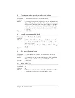
Страница 35: ...ommand ask for a value bigger than 8 bits bigger than 256 the following prefixes must be added d for a 16 bits value l for a 32 bits value f for a floating value Example to set the Speed D l20000 l20000 To better understand this protocol please refer to the following simple test Set the connection configuration presented in section 4 3 Start a terminal emulator on your host computer with the seria...

Страница 36: ...alue 16bits Answer c Effect Configure the actual firmware state The configuration array is to be seen as a table Each line in the table means a parameter and a value may be associated with Syntax C 0 d3 Index Default Value Description 0 0b00000100 Decide how many US sensor will be active See the table bellow for supported configurations 1 3 Decide the maximum echo numbers 2 0 Not Used 3 0 Not used...

Страница 37: ...b00011000 24 US sensor 4 to 5 US1TO3 0b00000111 7 US sensor 1 to 3 US2TO4 0b00001110 14 US sensor 2 to 4 US3TO5 0b00011100 28 US sensor 3 to 5 US1TO4 0b00001111 15 US sensor 1 to 4 US2TO5 0b00011110 30 US sensor 2 to 5 USALL 0b00011111 31 All US sensors D Set speed Command D speed motor left 32bits speed motor right 32bits Answer d Effect Set the speed of the two motors See in section 3 2 1 to cal...

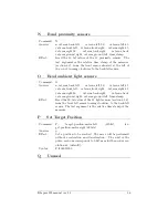
Страница 38: ...Ampl4 Time4 Dist5 Ampl5 Time5 Noise Effect Retrieve US measures from a given sensor number The sensor number is supposed to be 1 to 5 Syntax G 3 Example g 1 27 2900 100000 0 0 0 0 0 0 0 0 0 0 0 0 1800 H Configure the PID controler Command H T 16bits Kp 16bits Ki 16bits Kd 16bits Answer h Effect Set the proportional Kp the integral Ki and the deriva tive Kd parameters of the T regulator where T can...

Страница 39: ...le Led Command K LED 8bits State 8bits Answer k Effect Set the state of the two Programmable Leds see section 3 1 3 Led 5 6 LED select which one must be set 0 led 5 1 Led 6 State select the operation 0 OFF 1 ON 2 Change state Syntax K 0 1 L Set speed open loop Command L speed motor left 32bits speed motor right 32bits Answer l Effect Set the speed of the two motors without a PID controller Where a...

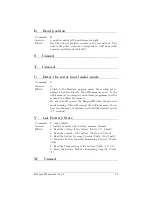
Страница 40: ...val sens left 90 val sens left 45 val sens front left val sens front right val sens right 45 val sens right 90 val sens back right val sens back val sens ground right val sens ground left time stamp Effect Read the 10 bit values of the 11 light sensors section3 1 6 from the front left sensor turning clockwise to the back left sensor The last argument is the relative time stamp of the measure P Set...

Страница 41: ... be required to reflash the memory Do not turn off or reset the KheperaIII when the uploader mode running This will corrupt the dsPic memory If you have run the mode by mistake wait until the timeout occurs 5 7 seconds V Get Battery State Command V index 8bits Answer v battery measure unit battery measure decimal Effect 0 Read the voltage of the battery Units 1V 0 1mV 1 Read the current of the bat...

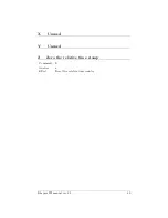
Страница 42: ...X Unused Y Unused Z Zero the relative time stamp Command Z Answer z Effect Reset the relative time counter Khepera III manual ver 2 2 40 ...

Страница 43: ......

Отзывы: