


Klein + Hummel
Operating Manual KPA Series
English
10
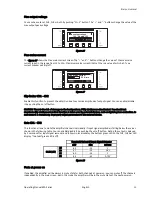
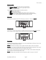
Connecting K8 Inputs
ANALOG INPUTS
DIGITAL INPUT (OPTIONAL)
OUTPUTS
XLR ANALOG: 1= GND, 2= IN+, 3= IN-
JACK: SLV. = GND, TIP= IN+, RING= IN-
XLR AES/EBU: 1= GND, 2= IN+, 3= IN-
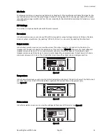
POS OUTPUT:
1+/2+ (PARALLEL)
NEG OUTPUT:
1-/2- (PARALLEL)
BRIDGEMODE:
USE OUT1 1+/2+ and OUT2 1-/2-
ANALOG INPUTS
DIGITAL INPUT (OPTIONAL)
OUTPUTS
XLR ANALOG: 1= GND, 2= IN+, 3= IN-
JACK: SLV. = GND, TIP= IN+, RING= IN-
XLR AES/EBU: 1= GND, 2= IN+, 3= IN-
POS OUTPUT:
1+/2+ (PARALLEL)
NEG OUTPUT:
1-/2- (PARALLEL)
BRIDGEMODE:
USE OUT1 1+/2+ and OUT2 1-/2-
ANALOG INPUTS
DIGITAL INPUT (OPTIONAL)
OUTPUTS
XLR ANALOG: 1= GND, 2= IN+, 3= IN-
JACK: SLV. = GND, TIP= IN+, RING= IN-
XLR AES/EBU: 1= GND, 2= IN+, 3= IN-
POS OUTPUT:
1+/2+ (PARALLEL)
NEG OUTPUT:
1-/2- (PARALLEL)
BRIDGEMODE:
USE OUT1 1+/2+ and OUT2 1-/2-
ANALOG INPUTS
DIGITAL INPUT (OPTIONAL)
OUTPUTS
XLR ANALOG: 1= GND, 2= IN+, 3= IN-
JACK: SLV. = GND, TIP= IN+, RING= IN-
XLR AES/EBU: 1= GND, 2= IN+, 3= IN-
POS OUTPUT:
1+/2+ (PARALLEL)
NEG OUTPUT:
1-/2- (PARALLEL)
BRIDGEMODE:
USE OUT1 1+/2+ and OUT2 1-/2-
K8 IN
K8 IN
K8 LINK
K8 LINK
S
W
KPA Series
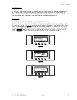
K8 INDICATORS
S= Sync W= Wink
Please refer to manual for proper
K8 INDICATORS
S= Sync W= Wink
Please refer to manual for proper
K8 INDICATORS
S= Sync W= Wink
Please refer to manual for proper
K8 INDICATORS
S= Sync W= Wink
Please refer to manual for proper
ON
STANDBY
AES/EBU ANALOG
CLASS
2
W
IRING
CLASS
2
WIRING
2
1
4
3
TERM
+VDC GND
+VDC GND
PUSH
PUSH
W
ARNING
T
o
reduce
the
risk
of
fire
or
electric
shock,
do
not
expose
this
app
aratus
to
rain
or
moisture
W
ARNING
To
reduce
the
risk
of
fire
or
electric
shock,
do
not
expose
this
app
aratus
to
rain
or
moisture
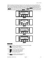
ANALOG IN1
ANALOG IN1
OUT1
OUT2
ANALOG IN2
AES/EBU
ANALOG IN2
AES/EBU
INPUT TIE ON OFF
INPUT TIE ON OFF
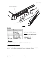
figure 6
The KPA series amplifiers have K8 input and link connections built in as a standard feature. A K8 digital audio
distribution line may be connected to the K8 IN connection on the rear of the amplifier via a standard Cat5-cable
terminated with an RJ-45 connector. The LINK connection may be used to daisy chain the K8 bus to the next
amplifier or other K8 device.
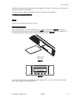
Channel selection is made using rotary switches behind the front panel of the amplifier. Any stereo pair of the
available 16 audio channels on the K8 bus may be selected. For example, channels 1&2, 3&4, etc. may be selected.
figure 7
The LED labelled “S” on the K8 connector indicates that a good K8 signal is present on the bus and the amplifier is
Synchronized to it.
The LED labelled “W” on the K8 connector is used to Wink, or flash on and off, to identify the amplifier when being
remote controlled in software.
The K8 TERM switches must all be set to ON when the amplifier is the last device in the K8 daisy chain. When the
LINK connection is in use, the termination must be set to OFF.
Please see the user manual for the K8 input devices for more extensive information on how to use and configure a
K8 bus. The KPA amplifier is compatible with any K8 input device including K8-AESI16 AES digital inputs,
K8-AI8 analog inputs and K8-ESB Ethersound bridge as well as new ones being offered in the future.
Channel Select Switch


