


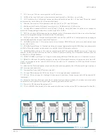


RS485 XLR link
USb Connection from a PC
RS485 XLR link
RS485 XLR link
RS485 XLR link
REV. A
KMT12/KMT18
13
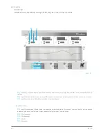
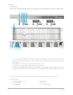
1)
CH1 Line Input. XLR line level input with +4 dBu sensitivity.
2)
CH2 Mic/Line Input. XLR input, with selectable sensitivity for Mic (-30 dBu) or Line (+4 dBu).
3)
CH1 Parallel Line Out. XLR parallel output, providing a direct signal from the CH1 Line Input. This output cannot
be processed or controlled via the K-Framework software.
4)
Phantom Power switch. Turns phantom power (48V) on/off on CH1 and CH2 inputs.
5)
Mic/Line switch. Selects CH2 input sensitivity for Mic ( -30 dBu) or Line ( +4 dBu) level.
6)
Limiting LEDs. Independent LEDs for the CH1 and CH2 inputs, which blink when the optical limiter engages to
protect the corresponding preamp circuit. Limiter threshold is +5 dBu.
7)
DSP Out. Auxiliary XLR balanced output, controlled via the K-Framework software. Users can select the signal
routed to this output and manage its amplitude and EQ individually.
8)
DSP Out Power switch. Turns phantom power (48V) on and off on the DSP out. Phantom power can be engaged
to drive additional wireless signal transmitters/receivers.
9)
AES/EBU Digital Input. XLR input connector for two-channel AES/EBU digital audio, accepting sample rates
from 32 kHz – 96 kHz.
10)
AES/EBU Digital Output. XLR output, providing two-channel digital audio from AES/EBU Input, at a sample rate
of 48 kHz. This output cannot be processed or controlled via the K-Framework software.
11)
REMOTE RS485 Link Input. XLR input for connecting the KMT from another RS485 device in a K-Framework
network. RS485 Link Input can also be used to connect a computer running the K-Framework software (requires
K-USB USB-to-RS485 adapter).
12)
REMOTE RS485 Link Output. XLR output for connecting additional RS485 devices in a K-Framework network.
13)
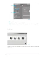
REMOTE USB Input. Connects a computer running the K-Framework software, for remote control of the KMT.
Users can manage an entire network of RS485 devices with one PC connected via USB (see RS485 Network
diagram, below).
14)
Speaker Out. Powered Speakon output, used to drive passive speakers, like a KP series mid-high module or a
KMT series passive subwoofer
15)
Power switch. Turns the KMT system on and off.
16)
AC Input. Powercon input for AC power. See p. 11 for voltage and power requirements.
17)
AC Link. Powercon ouput for feeding AC mains power to additional K-array components with a powercon AC
input socket.
18)
Extension Connector. Multi-pin connector for various K-array extension modules, for wireless control and audio
transmission, memory extension, digital signal encoding and audio reproduction.
19)
Power On LED. Indicates the system is ON.
20)
TOUCH SCREEN Control panel. Provides access to the main functions of the DSP on board (see Section 8.5)
RS485 network
Содержание Kobra KK52
Страница 1: ...KK52 KK102 USER S MANUAL English Kobra ...
Страница 2: ......
Страница 4: ...KK52 KK102 REV A 4 ...
Страница 6: ...KK52 KK102 REV A 6 ...
Страница 12: ...KK52 KK102 REV A 12 9 COVERAGE Img1 Flood coverage Img2 Spot coverage ...
Страница 13: ...REV A KK52 KK102 13 Img3 Array spot coverage Img4 Array Downfill application ...
Страница 22: ...KK52 KK102 REV A 22 ...
Страница 25: ...KMT12 KMT18 USER S MANUAL English ...
Страница 26: ...KMT12 KMT18 REV A 2 ...
Страница 28: ...KMT12 KMT18 REV A 4 ...
Страница 30: ...KMT12 KMT18 REV A 6 ...
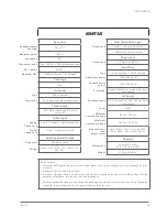
Страница 33: ...REV A KMT12 KMT18 9 7 PHYSICAL 32 5 cm 43 5 cm 33 5 cm 12 91 17 13 13 19 weight 15 6 kg 34 39 lbs KMT12 ...
Страница 34: ...KMT12 KMT18 REV A 10 61 cm 46 5 cm 47 5 cm 24 02 18 31 18 70 weight 27 6 kg 60 85 lbs KMT18 ...


