


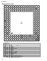
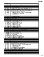


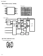


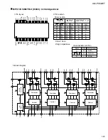

XM-PX50WT
1-8
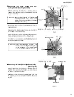
Unsolder the part g on the flexible wire extending
from the underside of the Chassis assembly to the
spindle motor.
1.
Remove the three screws I attaching the spindle
motor.
2.
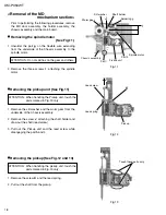
Removing the spindle motor
(See Fig.11)
Remove the slit washer and the worm gear from the
underside of the Chassis assembly.
Remove the screw J attaching the shaft holder and
draw out the shaft (lead screw).
Pull out the Pickup unit and the lead screw while
disengaging the part h and i.
1.
2.
3.
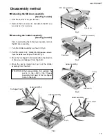
Removing the pickup unit (See Fig.11)
Prior to performing the following procedures, remove
the MD door assembly, the holder assembly, the
chassis assembly and the main board.
<Removal of the MD
mechanism section>
Do not spill flux on the gear and others.
ATTENTION:
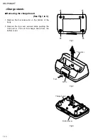
When handling the Pickup unit, touch the
parts marked in Fig.13 only.
ATTENTION:
Remove the screw K and the lead spring.
Pull out the shaft from the pickup.
1.
2.
Removing the pickup (See Fig.12 and 13)
When handling the pickup unit, touch the
parts marked in Fig.13 only.
ATTENTION:
Lead screw
K
Lead spring
Touch these parts only.
Worm gear
Slit washer
I
J
Shaft holder
Spindle motor
Soldering g
Part h
Part i
Chassis assembly
Fig.11
Fig.12
Fig.13
Pickup unit
Pickup