


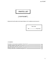
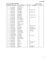
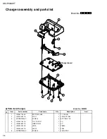


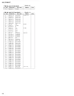


XM-PX50WT
3-7
Item
Parts number
Parts name
Area
Electrical parts list
Remarks
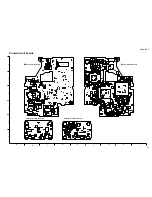
Block No. 01
A
Item
Parts number
Parts name
Area
Remarks
A
Q 502
DTA143TE-X
TRANSISTOR
Q 901
FMMT617-X
TRANSISTOR
Q 904
DTA124XUA-X
TRANSISTOR
Q 906
SSM3K01F-X
MOS FET
Q 961
DTA143TE-X
TRANSISTOR
Q 964
SSM3J01F-X
FET
Q 965
DTC144EE-X
TRANSISTOR
Q 966
DTA143TE-X
TRANSISTOR
R 60
NRSA6AJ-472W
MG RESISTOR
R 61
NRSA6AJ-474W
MG RESISTOR
R 62
NRSA6AJ-474W
MG RESISTOR
R 64
NRSA6AJ-474W
MG RESISTOR
R 101
NRSA6AJ-223W
MG RESISTOR
R 103
NRSA6AJ-392W
MF RESISTOR
R 111
NRSA6AJ-100W
MG RESISTOR
R 112
NRSA6AJ-392W
MF RESISTOR
R 113
NRSA6AJ-103W
MG RESISTOR
R 201
NRSA6AJ-223W
MG RESISTOR
R 203
NRSA6AJ-392W
MF RESISTOR
R 211
NRSA6AJ-100W
MG RESISTOR
R 212
NRSA6AJ-392W
MF RESISTOR
R 213
NRSA6AJ-103W
MG RESISTOR
R 301
NRZ0053-R22X
MG RESISTOR
R 303
NRSA6AJ-124W
MG RESISTOR
R 304
NRSA63J-1R0X
MG RESISTOR
R 305
NRSA6AJ-122W
MG RESISTOR
R 306
NRSA6AJ-124W
MG RESISTOR
R 307
NRSA6AJ-104W
MG RESISTOR
R 308
NRSA6AJ-0R0W
MG RESISTOR
R 310
NRSA6AJ-562W
MG RESISTOR
R 311
NRSA6AJ-103W
MG RESISTOR
R 314
NRSA6AJ-104W
MG RESISTOR
R 315
NRSA6AJ-133W
MG RESISTOR
R 316
NRSA6AJ-243W
MG RESISTOR
R 317
NRSA6AJ-104W
MG RESISTOR
R 318
NRSA6AJ-103W
MG RESISTOR
R 320
NRSA6AJ-563W
MG RESISTOR
R 321
NRSA6AJ-331W
MG RESISTOR
R 322
NRSA6AJ-331W
MG RESISTOR
R 323
NRSA6AJ-331W
MG RESISTOR
R 324
NRSA6AJ-102W
MG RESISTOR
R 325
NRSA6AJ-331W
MG RESISTOR
R 326
NRSA6AJ-331W
MG RESISTOR
R 328
NRSA6AJ-101W
MG RESISTOR
R 335
NRSA6AJ-102W
MG RESISTOR
R 336
NRSA6AJ-102W
MG RESISTOR
R 337
NRSA6AJ-102W
MG RESISTOR
R 338
NRSA6AJ-102W
MG RESISTOR
R 339
NRSA63J-100X
MG RESISTOR
R 341
NRSA6AJ-562W
MG RESISTOR
R 351
NRSA63J-1R0X
MG RESISTOR
R 352
NRSA63J-1R0X
MG RESISTOR
R 353
NRSA63J-1R0X
MG RESISTOR
R 354
NRSA6AJ-104W
MG RESISTOR
R 355
NRSA6AJ-0R0W
MG RESISTOR
R 356
NRSA6AJ-0R0W
MG RESISTOR
R 357
NRSA6AJ-0R0W
MG RESISTOR
R 364
NRSA6AJ-101W
MG RESISTOR
R 366
NRSA6AJ-101W
MG RESISTOR
R 367
NRSA6AJ-472W
MG RESISTOR
R 369
NRSA6AJ-102W
MG RESISTOR
R 371
NRSA6AJ-103W
MG RESISTOR
R 372
NRSA6AJ-104W
MG RESISTOR
R 373
NRSA6AJ-684W
MG RESISTOR
R 376
NRSA6AJ-332W
MG RESISTOR
R 377
NRSA6AJ-102W
MG RESISTOR
R 378
NRSA6AJ-105W
MG RESISTOR
R 379
NRSA6AJ-102W
MG RESISTOR
R 380
NRSA6AJ-151W
MG RESISTOR
R 385
NRSA6AJ-103W
MG RESISTOR
R 386
NRSA6AJ-103W
MG RESISTOR
R 387
NRSA6AJ-103W
MG RESISTOR
R 388
NRSA6AJ-103W
MG RESISTOR
R 400
NRSA6AJ-474W
MG RESISTOR
R 402
NRSA63J-1R0X
MG RESISTOR
R 450
NRSA6AJ-223W
MG RESISTOR
R 451
NRSA6AJ-223W
MG RESISTOR
R 454
NRSA6AJ-474W
MG RESISTOR
R 455
NRSA63J-1R0X
MG RESISTOR
R 459
NRSA6AJ-105W
MG RESISTOR
R 460
NRSA63J-225X
MG RESISTOR
R 461
NRSA6AJ-333W
MG RESISTOR
R 463
NRSA6AJ-0R0W
MG RESISTOR
R 466
NRSA63J-1R0X
MG RESISTOR
R 501
NRSA6AJ-473W
MG RESISTOR
R 503
NRSA6AJ-273W
MG RESISTOR
R 504
NRSA6AJ-473W
MG RESISTOR
R 506
NRSA6AJ-0R0W
MG RESISTOR
R 507
NRSA6AJ-273W
MG RESISTOR
R 508
NRSA6AJ-222W
MG RESISTOR
R 509
NRSA6AJ-104W
MG RESISTOR
R 510
NRSA6AJ-103W
MG RESISTOR
R 511
NRSA6AJ-474W
MG RESISTOR
R 512
NRSA6AJ-474W
MG RESISTOR
R 513
NRSA6AJ-474W
MG RESISTOR
R 514
NRSA6AJ-474W
MG RESISTOR
R 516
NRSA6AJ-473W
MG RESISTOR
R 517
NRSA6AJ-102W
MG RESISTOR
R 518
NRSA6AJ-104W
MG RESISTOR
R 519
NRSA6AJ-564W
MG RESISTOR
R 520
NRSA6AJ-104W
MG RESISTOR
R 521
NRSA6AJ-564W
MG RESISTOR
R 522
NRSA6AJ-474W
MG RESISTOR
R 523
NRSA6AJ-474W
MG RESISTOR
R 524
NRSA6AJ-103W
MG RESISTOR
R 525
NRSA6AJ-103W
MG RESISTOR
R 527
NRSA6AJ-474W
MG RESISTOR
R 529
NRSA6AJ-0R0W
MG RESISTOR
R 530
NRSA6AJ-0R0W
MG RESISTOR
R 601
NRSA6AJ-474W
MG RESISTOR
R 603
NRSA6AJ-474W
MG RESISTOR
R 604
NRSA6AJ-474W
MG RESISTOR
R 613
NRSA6AJ-4R7W
MG RESISTOR
R 901
NRSA6AJ-562W
MG RESISTOR
R 908
NRSA6AJ-0R0W
MG RESISTOR
R 909
NRSA6AJ-124W
MG RESISTOR
R 922
NRSA63J-0R0X
MG RESISTOR
R 961
NRSA6AJ-221W
MG RESISTOR
R 962
NRSA6AJ-474W
MG RESISTOR
R 965
NRSA6AJ-474W
MG RESISTOR
R 966
NRSA6AJ-472W
MG RESISTOR
R 967
NRSA6AJ-220W
MG RESISTOR
S 60
NSW0140-001X
DETECT SWITCH
S 501
NSW0117-001X
SLIDE SWITCH
S 502
NSW0134-001X
TACT SWITCH
ALPS
S 503
NSW0134-001X
TACT SWITCH
ALPS
(Main board)
S 504
NSW0134-001X
TACT SWITCH
ALPS
X 300
NAX0439-001X
CRYSTAL
X 500
NAX0427-001X
C RESONATOR