(No.MB057)1-9
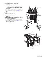
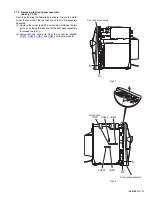
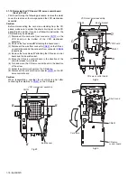
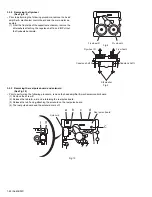
3.1.3 Removing the rear panel / fan assembly
(See Fig.5,6)
• Prior to performing the following procedure, remove the metal
cover and the rear cover.
(1) Remove the twelve screws
E
attaching the rear panel.
Release the two joints
a
on the rear side and the two joints
b
on each side.
(2) Remove the two screws
F
attaching the fan bracket and
release the two joints
d
on the rear panel, and remove.
(3) Disconnect the wire from the connector
CN908
on the main
board.
Reference:
The MIC volume board comes off.
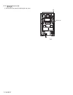
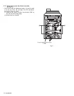
3.1.4 Removing the MIC volume board
(See Fig.6)
• Prior to performing the following procedure, remove the metal
cover, the rear cover and the rear panel.
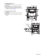
(1) Remove the two screws
G
attaching the MIC volume board
on the inside of the rear panel.
(2) Disconnect the wire from connector
CN906
on the main
board on the back of the body.
Fig.5
Fig.6
Rear panel
Fan assembly
E
E
E
E
E
F
E
F
d
d
a
b
b
Main board
Mic volum board
CN908
CN906
Rear panel
G
Содержание =UX-J55V
Страница 19: ... No MB057 1 19 Fig 26 Card wire Short round Pick up board ...
Страница 47: ... M E M O ...

