


(No.MB057)1-11
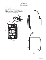
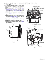
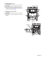
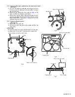
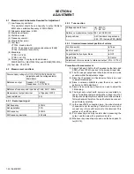
3.1.7 Removing the main board / the heat sink board / the speaker board / the vocal cancel board
(See Fig.9~11)
• Prior to performing the following procedure, remove the metal
cover, the rear cover, the rear panel, and the VCD mechanism
assembly.
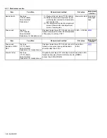
(1) Remove the two screws
K
attaching the main board.
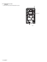
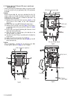
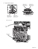
(2) Disconnect the card wire from the connector
CN900
,
CN901
,
CN930
,
CN931
and
CN932
, and disconnect the
wire from the connector
CN907
and
CN916
,
CN917
on the
main board.
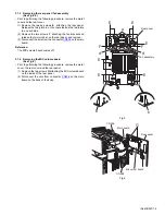
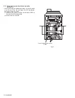
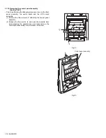
(3) Remove the band and disconnect the wire from the
connector
CN951
on the power transformer assembly, and
then remove the main board / the heat sink board from the
body.
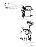
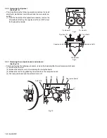
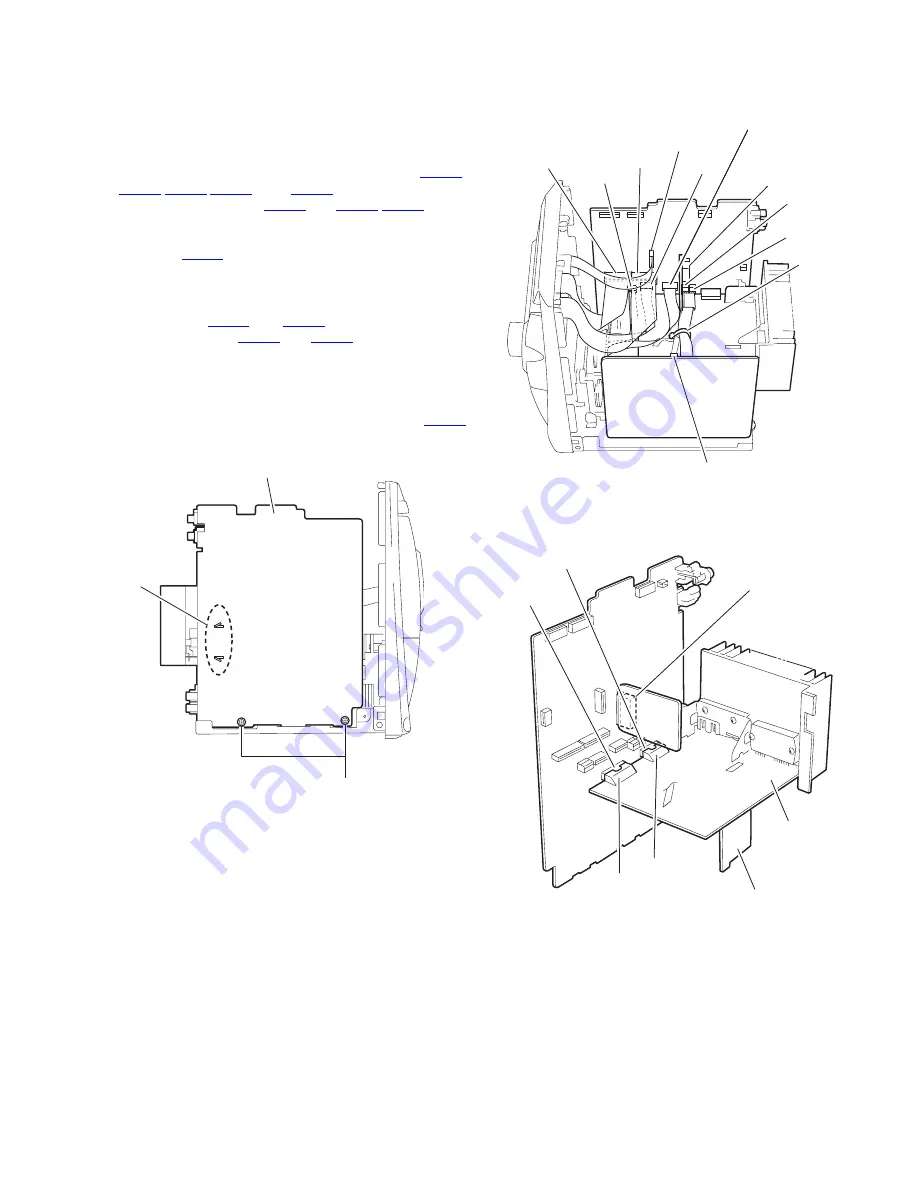
(4) Release the two joints
g
of the main board and disconnect
the connector
CN944
and
CN945
of the heat sink board
from the connector
CN912
and
CN911
of the main board
respectively, and remove.
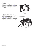
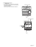
(5) Remove the two screws
L
and the two screws
M
attaching
the heat sink.
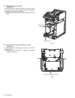
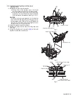
(6) Remove the screw
N
attaching the speaker board.
(7) Disconnect the vocal cancel board from connector
CN905
on the main board.
Fig.9
Fig.10
Fig.11
H
g
Main board
Power transformer assembly
CN951
CN930
CN916
CN900
CN901
CN917
CN931
CN907
CN932
Band
Main board
CN905
Vocal cancel board
CN944
CN945
CN912
CN911
CN905
Heat sink board
Main board
Vocal cancel board
Speaker board
Содержание =UX-J55V
Страница 19: ... No MB057 1 19 Fig 26 Card wire Short round Pick up board ...
Страница 47: ... M E M O ...


