background image

2-5

Parts are safety assurance parts.
When replacing those parts make
sure to use the specified one.

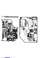
Front section

C5004

IC500

B5532

IC565

R5101

R5102

C5011

D5002

S5101

S5102

Q5000

R5602

R5601

J5500

R5604

S5100

J5600

C5003

C5001

R5200

C5000

C5600

C5601

C5504

C5503

CN550

R5600

R5109

R5108

C5009

C5005

C5002

IC566

CN500

D5601

DI500

C5660

R5202

R5107

R5106

S5108

C5200

S5107

S5106

C5661

S5105

R5100

D5200

R5103

S5103

R5501

R5603

R5607

R5605

R5662

R5663

R5104

R5105

C5662

S5104

S5109

IC501

C5663

R5664

R5665

R5667

R5666

R5669

R5660

R5668

C5664

D5660

R5661

JS500

R5672

R5671

C5012

R5000

C5006

C5007

C5500

D5600

R5001

C5008

D5206

C5502

R5002

C5602

R5204

C5010

D5205

Q5660

R5001

C5501

R5673

R5674

0.01/50

PT6315

0

RC4558D-X

2.4k

3.9k

NI

SLI-343URC-W-T

QSW0683-001Z

QSW0683-001Z

KRC102S-X

30k

24k

QNS0173-001

30k

QSW0683-001Z

QNS0173-001

NI

0.01/50

47

0.01/50

NI

NI

NI

0.001/50

QGF1205C2-10

1k

15k

6.8k

0.01/50

NI

NI

!

RC4558D-X

QGF1205F2-14

QLF0165-001

2.2/50

100k

3.9k

2.4k

QSW0683-001Z

0.01/50

QSW0683-001Z QSW0683-001Z

2.2/50

QSW0683-001Z

910

SELU1E54CM-P

6.8k

QSW0683-001Z

1k

24k

NI

NI

100K

100K

15k

910

47/25

QSW0683-001Z

QSW0683-001Z

GP1UM271XKVF

47/25

4.7K

4.7K

4.7K

4.7K

100K

NI

220K

10/50

NI

QSW1059-001

9.1k

NI

NI

10k

0.1/16

82k

NI

NI

0.01/50

NI

NI

0.001/50

1k

0.0022/50

330

47/10

KRC109S-X

NI

NI

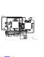
P16

REMOCON

DICK

DIDT

DICS

G2

G3

G4

G5

G6

G7

G8

G9

G10

P8

P9

P10

P11

P12

P13

P14

P15

REMOCON

DICK

P6

DICS

DIDT

P5

P7

P8

P9

P16

P15

G1

P14

P13

P1

P12

P11

P2

P3

P10

P4

P5

P6

P7

P4

P3

G10

G9

G8

G7

G6

G5

G4

G3

G2

G1

P1

P2

Содержание UX-GB9DABB

Страница 1: ...TEM MB542 2006 7 UX GB9DABB UX GB9DABE UX GB9DABEN Lead free solder used in the board material Sn Ag Cu melting point 219 Centigrade TABLE OF CONTENTS 1 PRECAUTION 1 3 2 SPECIFIC SERVICE INSTRUCTIONS 1 7 3 DISASSEMBLY 1 8 4 ADJUSTMENT 1 19 5 TROUBLE SHOOTING 1 21 CA UXGB9DAB SP UXGB9DAB SP UXGB9DAB ...

Страница 2: ...g range 522 kHz 1 629 kHz DAB tuning range Band III 174 928 MHz 239 200 MHz L Band 1 452 960 MHz 1 490 624 MHz CD player section Dynamic range 88 dB Signal to noise ratio 93 dB Wow and flutter Immeasurable Speakers Speaker units 10 cm cone 1 1 5 cm dome 1 Impedance 6 Ω Dimensions approx 140 mm 231 mm 195 mm W H D Mass approx 1 7 kg each General Power requirement AC 230 V 50 Hz Power consumption 60...

Страница 3: ...ack control shafts etc to be sure the product is safe to operate without danger of electrical shock Do not use a line isolation transformer during this check Plug the AC line cord directly into the AC outlet Using a Leakage Current Tester measure the leakage current from each exposed metal parts of the cabinet particular ly any exposed metal part having a return path to the chassis to a known good...

Страница 4: ...same safety characteristics as the recommended replacement parts shown in the Parts List of the Service Manual and may create shock fire or other hazards 4 The leads in the products are routed and dressed with ties clamps tubings barriers and the like to be separated from live parts high temperature parts moving parts and or sharp edges for the prevention of electric shock and fire hazard When ser...

Страница 5: ...of the laser diode in the optical pickup The tester s internal power source can easily destroy the laser diode 1 7 Handling the traverse unit optical pickup 1 Do not subject the traverse unit optical pickup to strong shocks as it is a sensitive complex unit 2 Cut off the shorted part of the flexible cable using nippers etc after replacing the optical pickup For specific details refer to the replac...

Страница 6: ... uses visible and or invisible laser radiation and is equipped with safety switches which prevent emission of radiation when the drawer is open and the safety interlocks have failed or are defeated It is dangerous to defeat the safety switches 5 CAUTION If safety switches malfunction the laser is able to function 6 CAUTION Use of controls adjustments or performance of procedures other than those s...

Страница 7: ... No MB542 1 7 SECTION 2 SPECIFIC SERVICE INSTRUCTIONS This service manual does not describe SPECIFIC SERVICE INSTRUCTIONS ...

Страница 8: ...ne screw A attaching the rear cover See Fig 1 2 Remove the five screws B attaching the side panel and top cover See Fig 1 3 Remove the two screws C attaching the front panel assem bly See Fig 2 4 Slide the both side panels in the direction of the arrow See Fig 3 Fig 1 Fig 2 Fig 3 B B A C both side Side panel ...

Страница 9: ...wo screws D attaching the front panel and top cover 2 Disconnect the card wire of the switch board from the con nector CN401 of the micon board 3 Remove the one screw E attaching the earth wire on the micon board 4 Disengage the two hooks a then remove the front panel as sembly Fig 4 D CN401 a a E ...

Страница 10: ...the micon board from the power amplifier board in the direction of the arrow while releasing the claw b c of the connectors CN151 CN152 on the power amplifier board See Fig 7 4 Remove the one screw J attaching the micon board See Fig 5 3 1 6 Removing the power amplifier board See Fig 6 7 1 Remove the two screws K attaching the IC bracket See Fig 6 2 Remove the one screw L attaching the power ampli...

Страница 11: ...9 10 1 Disconnect the connector wire from the connector CN900 of the trans board See Fig 9 2 Remove the two screws N attaching the trans board See Fig 9 3 Remove the three screws P attaching the power transform er and the trans shield See Fig 10 Fig 9 Fig 10 3 1 9 Removing the heat sink See Fig 6 1 Remove the four screws Q attaching the heat sink M CN900 N Trans board P P ...

Страница 12: ...ig 11 Fig 11 3 1 11 Removing the jack board See Fig 12 1 Remove the two screws S attaching the jack board 2 Disengage the two hooks f then remove the jack board Fig 12 3 1 12 Removing the switch board See Fig 13 1 Take out the volume knob 2 Remove the six screws T attaching the switch board 3 Disengage the two hooks g then remove the switch board Fig 13 e Rear panel f S T T g g ...

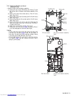
Страница 13: ...g 1 3 2 2 Removing the tray assembly See Fig 2 and 3 Remove the CD cover 1 Press slide cam and pull out the tray assembly to direction of the arrow from right side of CD mechanism assembly See Fig 2 2 Remove the two screws B attaching the tray assembly from upper side of CD mechanism See Fig 3 3 Remove the bussing of the tray assembly from boss c of the CD mechanism assembly and remove the tray as...

Страница 14: ...CD mechanism assem bly 2 Disconnect the card wire from connector CN602 of the CD servo board and then take out the traverse mechanism as sembly and CD servo board together Reference When reattaching the traverse mechanism assembly the card wire should through the part d Fig 4 CD mechanism assembly CN602 CD servo board C C d Card wire Traverse mechanism assembly ...

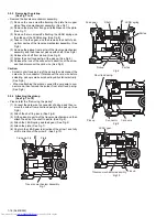
Страница 15: ...ard See Fig 5 6 Solder to short land part j of pickup See Fig 6 7 Release the lock of connector CN601 to direction of the ar row 2 and disengage the card wire See Fig 6 Caution Solder to short land part j of the pickup then disconnect the card wire from connector CN601 of the CD servo board If disconnect the card wire before soldering pickup is make sure destroyed by static electricity See Fig 6 W...

Страница 16: ...e pickup then disconnect the card wire from connector If disconnect the card wire before soldering pickup is make sure destroyed by static electricity See Fig 9 When reattaching the pickup connect the card wire to con nector and then remove the solder from short land part p See Fig 9 3 2 6 Attaching the pickup See Fig 7 to 10 Please refer the Removing the pickup 1 Connect the card wire to connecto...

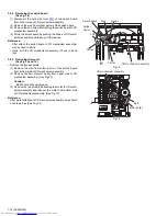
Страница 17: ...ttaching the plate See Fig 12 4 Disengage the plate from fixing part s and take out the plate See Fig 12 5 Remove the feed gear and take out the feed motor See Fig13 Reference When attaching the feed motor the wire has to through the part t of the traverse mechanism assembly See Fig 13 Fig 11 Fig 12 Fig 13 Traverse mechanism assembly CD servo board Yellow wire White wire Soldered part q Soldered p...

Страница 18: ...nism assembly it have to bond lock 3 2 9 Removing the motor See Fig 14 and 15 Remove the tray assembly 1 Remove the wire from solder part u of the switch board from bottom side of CD mechanism assembly 2 Remove the belt of motor pulley from upper side of CD mechanism assembly See Fig 15 Caution Belt should not apply grease 3 Remove the two screws J attaching the motor to CD mech anism assembly and...

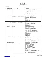
Страница 19: ...ode Pressing DIMMER key at Power Standby NG Safety trigger NG 3 Press any key except SOUND TURBO on the unit or CANCEL key remocon will exit test mode 4 5 remocon A STANDBY SET AHB PRO remocon A STANDBY SET BASS TREBLE 1 Display ROM version for 5 seconds 2 Example 37R06107 Digit 1 and 2 ROM version 37 Digit 3 and 4 ROM Correction version 0 Digit 5 ROM issue year 2006 Digit 6 ROM issue month Januar...

Страница 20: ...blinking that under test mode 3 First display is syscon version display for 3 sec 4 Follow onward is DAB module version display 5 For info about DAB module under test mode press display key Syscon version temporary display Module Version SID Audio err Error ck EID FIC err MSC err To off this test mode follow step 1 the picture indicator will OFF blinking ...

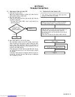
Страница 21: ...e whole optical block do not touch the semi fixed resistor If the laser power is lower than the specified value the la ser diode is almost worn out and the laser pickup should be replaced If the semi fixed resistor is adjusted while the pickup is functioning normally the laser pickup may be damaged due to excessive current 5 2 Replacement of laser pickup CD Is the level of RFOUT under 1 25V 0 22Vp...

Страница 22: ... No MB542 Audio Video Systems Category 10 1 1chome Ohwatari machi Maebashi city 371 8543 Japan Victor Company of Japan Limited VPT Printed in Japan ...

Страница 23: ... schematic diagrams Printed circuit boards 2 1 2 2 2 8 to 10 CD ROM No SML200607 MICRO COMPONENT SYSTEM No MB542SCH 2006 7 COPYRIGHT 2006 Victor Company of Japan Limited Lead free solder used in the board material Sn Ag Cu melting point 219 Centigrade CA UXGB9DAB SP UXGB9DAB SP UXGB9DAB ...

Страница 24: ...ponent parts appearing on the silk screen printed side parts side of the PWB diagrams the parts that are printed over with black such as the resistor diode and ICP or identified by the mark nearby are critical for safety ...

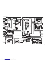
Страница 25: ... US5 6V REG D950 to D953 DIODE BRIDGE D900 to D903 DIODE BRIDGE D1401 to D1403 DIODE BRIDGE Trans section POUT RELAY POUT RELAY POUT RELAY SPK RELAY PRT SMUTE SMUTE CDL R S2UDT RXDO CPURST RESET TUL R DABL R TXDO U2SDT RX LIN RIN LIN RIN VOL DATA VOL CE VOL CLK AHB OUTL R SPK RELAY OUTL OUTR LOUT ROUT VH S2 F S1 S2 F F PRT L R FTU TUCE TUDIN TUCLK TUDOUT RDSCUT RDSCLK RDSDATA T950 POWER TRANS T900...

Страница 26: ...950 D952 D953 D903 D900 D901 B914 B915 C950 D950 C903 C901 C900 C951 D954 C952 C904 F900 D902 C902 1N4003S T5 QGB2510J1 13 KIA7805API QSK0129 002 0 0047 QQT0500 002 1N4003S T5 QQT0253 013 1SS133 T2 QGA7901C1 02 KTC3875 YG X 1N4003S T5 1N4003S T5 1N5402M 20 1N5402M 20 1N5402M 20 1000 25 1N4003S T5 NI NI NI NI 1SS133 T2 100 16 0 1 100 QMF51W2 R80 J8 1N5402M 20 NI Transformer section ...

Страница 27: ... C1600 C1601 D1600 R1600 Q1250 R1250 R1523 R1509 C1200 R1527 C1406 Q1651 Q1650 Q1000 C1403 R1528 R1503 C1515 C1516 C1508 C1509 R1504 STK432 050 E NI 56p 50 T1 6AL 250V 5p 50 5p 50 10 35 10 35 220 25 2A02 M 1K 1K 3K KTC3875 YG X 100 56K 56K KIA7809API KTC3875 YG X MTZJ9 1B T2 KIA278R12PI U P NI NI 3 3K 100 QGB2510K2 10 QNZ0136 001Z 10K 120K 100K 100K 82K 22 50 10K KTC3875 YG X 2200 35 2200 35 KRA10...

Страница 28: ... 2K 1K 10K 1K 1K 20K 2 2K 0 1 50 20K QNB0292 001 BR24L08F W X QGF1205F2 14 2 2K 1K QGF1036C2 17 15K 1K 2 2K KTA1504 YG X KTC2875 X 10K QGB2510J1 10 10K KRA102S X 4 7 50 KTC2875 X QQR0621 001Z 1K KIA78R33PI 10K 10K MN101C49KFG 2 2K 2 2K 2 2K 2 2K QGF1205F2 15 10K KTC3875 YG X KTC3875 YG X 47K 47K 51K 120K NI NI 150K 2 2K 2 2K 150K 10K 1K 2 2K QGF1036F2 13 QGF1205F2 10 10K 10K 10K 10K 10K 0 01 50 0 ...

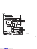
Страница 29: ...05 Q5660 R5001 C5501 R5673 R5674 0 01 50 PT6315 0 RC4558D X 2 4k 3 9k NI SLI 343URC W T QSW0683 001Z QSW0683 001Z KRC102S X 30k 24k QNS0173 001 30k QSW0683 001Z QNS0173 001 NI 0 01 50 47 0 01 50 NI NI NI 0 001 50 QGF1205C2 10 1k 15k 6 8k 0 01 50 NI NI RC4558D X QGF1205F2 14 QLF0165 001 2 2 50 100k 3 9k 2 4k QSW0683 001Z 0 01 50 QSW0683 001Z QSW0683 001Z 2 2 50 QSW0683 001Z 910 SELU1E54CM P 6 8k QS...

Страница 30: ...PD VSS0 ADCK ADCOVR NADCPSC NULMON FSYO CIRSYN CTLCLK CTLLR CTLDAT AGCDAT LVDD0 VSS1 SDAT2 MP2CLK MP2IN MP2W DAOUT VDD0 VSS2 RDIOUT SDOWD SDODT SDOCK DDODAT DDOCLK DDOERF DDOWMSC LVDD1 VSS3 DDOMNO0 DDOMNO1 DDOMNO2 DDOMNO3 DDOMNO4 DDOMNO5 DDOWFIC VDD1 VSS4 NIRQ MPUTX MPURX MPUCLK NMPUEN MPUMOD MDSPMO0 MDSPMO1 MVDD0 MVSS0 MDSPMO2 MDSPMO3 SDSPMO0 SDSPMO1 SDSPMO2 SDSPMO3 MVDD1 MVSS1 VSS5 LON VDD2 VDD3...

Страница 31: ...05 QGF1036F1 17 100 16 3 9k 5 6k NI NI 2SB1424 QR W 1 16 NI NI NQR0007 002X 47k 47k NI 150 NQR0007 002X 680 680 560 560 NI NI 0 0022 0 0022 100 QAX0684 001Z 2SB1424 QR W 10k 22 6 3 1k 0 1 16 47 6 3 1k 1k NI NI 0 100 6 3 0 1 16 NI 0 0 1 16 NI 0 1 16 0 1 680p 15k 15k 2 2k 4 7k 0 1 0 1 16 1k 1k 1k 1k 1k NAX0476 001X 10p 10p 0 1 1k 33k 1k 0 1 16 1 5k NI 0 18k 0 1 16 22k 4 7k 2 2k 220 10 2 2k 15k QSW10...

Страница 32: ... D1001 D1002 W1350 C1253 D1250 D1500 D1501 D1502 D1503 D1600 D1851 IC110 IC120 IC150 L1500 L1501 Q1000 Q1500 Q1501 Q1502 Q1600 Q1601 Q1650 Q1651 Q1652 Q1850 R1000 R1500 R1501 R1502 R1503 R1504 R1505 R1506 R1507 R1508 R1509 R1510 R1511 R1512 R1513 R1514 R1515 R1516 R1517 R1518 R1519 R1520 R1521 R1522 R1523 R1524 R1525 R1526 R1527 R1528 R1529 R1530 R1531 R1532 R1533 R1534 R1600 R1601 Q1851 R1652 R16...

Страница 33: ... R4025 R4026 R4027 R4028 R4029 R4030 R4031 R4032 R4033 R4036 R4037 R4038 R4039 R4040 R4041 R4043 R4044 CN400 R4046 R4047 R2102 R2101 R4052 R4053 R4054 R4055 R4060 R4061 R4062 R4063 R4064 R4065 R4066 R4067 C2215 R4070 R4200 D4203 D4204 R4203 X4000 C2206 C2205 C2228 C2229 Q2100 Q2007 D4005 D2301 D2300 D2302 W400 J2600 R4078 Q2006 R4076 R4077 R2009 R2010 R2107 PP400 Q2005 Q2002 Q2003 R2007 CN408 R200...

Страница 34: ... R807 R808 R809 R811 R812 R813 R814 R815 R816 R817 K250 SW601 X251 X651 M601 CN651 C851 Q851 R851 C252 C690 C291 C609 C612 C621 C622 C624 C631 C632 C633 C641 C643 C651 C655 C657 C663 C664 C665 C666 C667 C673 C674 C677 C678 C801 C802 C850 K252 K251 CN602 D601 D655 IC651 IC801 K654 Q291 Q631 Q652 R253 R254 R258 R267 R285 R286 R287 R288 R298 R617 R631 R632 R634 R635 R652 R653 R658 R662 R664 R669 R671...

Страница 35: ... M E M O ...
Страница 36: ...Victor Company of Japan Limited No MB542SCH Printed in Japan VPT Audio Video Systems Category 10 1 1chome Ohwatari machi Maebashi city 371 8543 Japan ...

Страница 37: ...ed view of general assembly and parts list Block No M1 CD mechanism assembly and parts list Block No MB CD loading base assembly and parts list Block No MD Electrical parts list Block No 01 05 Packing materials and accessories parts list Block No M3 UX GB9DABB UX GB9DABE UX GB9DABEN 3 2 3 5 3 7 3 9 3 14 No MB542 ...

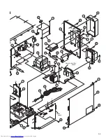
Страница 38: ...view of general assembly and parts list A c B C K K L L J D C a Block No M M M 1 Trans board Switch board Jack board Cover board f 14 51 4 10 3 6 10 29 2 5 8 52 1 28 27 7 50 47 49 17 54 53 15 16 19 55 26 57 9 34 33 ...

Страница 39: ...c A B J L J D F G b d b e a e B F G H E H E g Power amplifier board Micon board f d g 58 43 51 49 19 13 12 57 11 22 25 18 24 25 60 59 62 36 56 61 20 32 50 30 48 21 63 23 35 42 45 39 40 41 46 37 38 44 31 33 ...

Страница 40: ...CER x2 30 GV30842 001A IC BRACKET 31 GV40620 006A HEAT SINK 32 QYSBSG3010ZA TAP SCREW M3 x 10mm x2 33 GV40520 002A HEAT SINK 34 QYSBSG3010ZA TAP SCREW M3 x 10mm 35 GV20399 021A REAR PANEL 36 QAU0413 001 TUNER 37 QYSBSGY3008EA TAP SCREW M3 x 8mm x2 38 GV30841 002A HEAT SINK 39 QYSBSGY3008EA TAP SCREW M3 x 8mm x4 40 QYSBSGY3008EA TAP SCREW M3 x 8mm 41 QYSBSGY3008EA TAP SCREW M3 x 8mm x2 42 QYSBSGY30...

Страница 41: ... list Block No M M M B 18mm 3 5mm A A a a 0 1mm 12 0mm 0 1mm 0 1mm FTU JS1 1M Back side The parts without symbol number are not service 19 11 16 4 1 20 2 7 13 12 6 15 8 18 14 17 3 9 5 10 7 6 8 12 13 11 10 JVG 31N JVS 1003 FL 7750E Grease ...

Страница 42: ...855 002A TM CHASSIS 7 LV43468 001A T T ASSY 8 QAR0302 001 SPINDLE MOTOR 9 VKZ4743 002 SPECIAL SCREW x2 10 LV40157 001A SCREW SHAFT 11 LV43651 001A SS GEAR 12 LV43650 001A F MOTOR GEAR 13 QAR0303 001 FEED MOTOR 14 QYSPSPT2030MA SCREW M2 x 3mm 15 LV34565 002A F MIDDLE GEAR 16 LV34563 001A SHAFT HOLDER 17 QYSPSFT1740ZA TAP SCREW M1 7 x 4mm 18 QYSBSF2006ZA TAP SCREW M2 x 6mm x2 19 LV30225 073A SPACER ...

Страница 43: ... D 7 75mm 0 10mm h j h FMU MS1 1M Backside The parts without symbol number are not service c e d CD loading switch board f Back side e f c d g g j 1 13 11 2 3 9 10 4 15 18 15 17 6 16 14 12 26 20 19 25 24 23 21 27 21 23 22 23 22 23 8 5 7 JVS 1003 JVG 450 Grease ...

Страница 44: ...OADING MOTOR 10 LV43844 002A MOTOR PULLEY 11 QYSPSPU1730ZA SCREW M1 7 x 3mm x2 12 QYSDSF2008ZA TAP SCREW M2 x 8mm 13 LV43974 001A BELT 14 LV21852 003A CLAMPER BASE 15 QYSDSF2008ZA TAP SCREW M2 x 8mm x2 16 LV41741 004A SPECIAL SCREW 17 LV34586 002A CD CLAMPER 18 LV42930 003A P C MAGNET 18 or LV41118 003A P C MAGNET 19 LV43848 001A YOKE 20 LV43958 001A SPECIAL SCREW 21 LE40900 003A INSULATOR x2 22 L...

Страница 45: ...27 QFLC1HJ 104Z M CAPACITOR 0 1uF 50V J C2228 QFVF1HJ 184Z MF CAPACITOR 0 18uF 50V J C2229 QFVF1HJ 184Z MF CAPACITOR 0 18uF 50V J C2230 QFLC1HJ 104Z M CAPACITOR 0 1uF 50V J C2231 QETN1HM 226Z E CAPACITOR 22uF 50V M C2232 QFLC1HJ 104Z M CAPACITOR 0 1uF 50V J C2300 QETN1HM 106Z E CAPACITOR 10uF 50V M C2301 QETN1HM 105Z E CAPACITOR 1uF 50V M C2302 NCB31AK 154X C CAPACITOR 0 15uF 10V K C2310 QETN1HM 1...

Страница 46: ... RESISTOR 10kΩ 1 16W J R4073 NRSA63J 103X MG RESISTOR 10kΩ 1 16W J R4074 NRSA63J 222X MG RESISTOR 2 2kΩ 1 16W J R4075 NRSA63J 221X MG RESISTOR 220Ω 1 16W J R4076 NRSA63J 222X MG RESISTOR 2 2kΩ 1 16W J R4077 NRSA63J 102X MG RESISTOR 1kΩ 1 16W J R4078 NRSA63J 472X MG RESISTOR 4 7kΩ 1 16W J R4080 NRSA63J 472X MG RESISTOR 4 7kΩ 1 16W J R4081 NRSA63J 472X MG RESISTOR 4 7kΩ 1 16W J R4082 NRSA63J 222X MG...

Страница 47: ... 103X MG RESISTOR 10kΩ 1 16W J R1251 NRSA63J 223X MG RESISTOR 22kΩ 1 16W J R1500 NRSA63J 563X MG RESISTOR 56kΩ 1 16W J Symbol No Part No Part Name Description Local R1501 NRSA63J 102X MG RESISTOR 1kΩ 1 16W J R1502 NRSA63J 102X MG RESISTOR 1kΩ 1 16W J R1503 NRSA63J 182X MG RESISTOR 1 8kΩ 1 16W J R1504 NRSA63J 182X MG RESISTOR 1 8kΩ 1 16W J R1505 NRSA63J 102X MG RESISTOR 1kΩ 1 16W J R1506 NRSA63J 10...

Страница 48: ... 16W J R375 NRSA63J 103X MG RESISTOR 10kΩ 1 16W J R376 NRSA63J 221X MG RESISTOR 220Ω 1 16W J R377 NRSA63J 221X MG RESISTOR 220Ω 1 16W J R378 NRSA63J 221X MG RESISTOR 220Ω 1 16W J R379 NRSA63J 221X MG RESISTOR 220Ω 1 16W J R380 NRSA63J 0R0X MG RESISTOR 0Ω 1 16W J R382 NRSA63J 472X MG RESISTOR 4 7kΩ 1 16W J R383 NRSA63J 472X MG RESISTOR 4 7kΩ 1 16W J R384 NRSA63J 472X MG RESISTOR 4 7kΩ 1 16W J R385 ...

Страница 49: ...RSA63J 473X MG RESISTOR 47kΩ 1 16W J R611 NRSA63J 562X MG RESISTOR 5 6kΩ 1 16W J R613 NRSA63J 472X MG RESISTOR 4 7kΩ 1 16W J R617 NRSA63J 152X MG RESISTOR 1 5kΩ 1 16W J R631 NRSA63J 2R2X MG RESISTOR 2 2Ω 1 16W J R632 NRSA63J 3R9X MG RESISTOR 3 9Ω 1 16W J R634 NRSA63J 3R9X MG RESISTOR 3 9Ω 1 16W J R635 NRSA63J 100X MG RESISTOR 10Ω 1 16W J R636 NRSA63J 151X MG RESISTOR 150Ω 1 16W J R651 NRSA63J 472X...

Страница 50: ... Packing materials and accessories parts list Block No M M M 3 No additional supplemental order of WARRANTY CARDs are available P5 A1 A5 A6 A7 A8 A9 A10 A3 P2 P3 P6 A2 P4 P8 P8 P7 P9 P1 A11 A12 A13 A13 A11 ...

Страница 51: ...ARRANTY CARD BT 54028 1 A 7 QAL0014 003 AM LOOP ANT A 8 QAL0457 001 ANT WIRE A 9 QAL0858 001 ANT WIRE A 10 VNA3000 204 REGIST CARD B A 11 UXGB9DAB SPBOX SPEAKER BOX x2 A 12 J201 XG3503G 50 SPK NET ASSY x2 A 13 441 910102 00 RUBBER CUSHION x8 P 1 GV20451 002A CARTON ASSY P 2 GV10299 001A CUSHION UPPER P 3 GV10298 001A CUSHION BOTTOM P 4 GV30852 001A CARTON SPACER P 5 QPC02503515P POLY BAG 25cm x 35...

Отзывы: