(No.MB542)1-17
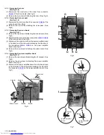
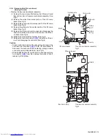
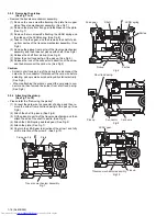
3.2.7 Removing the feed motor
(See Fig.11 to 13)
• Remove the traverse mechanism.
(1) Remove the yellow wire from solder part
q
of the CD servo
board from upper side of traverse mechanism. (See Fig.11)
(2) Remove the white wire from solder part
r
of the CD servo
board. (See Fig.11)
(3) Remove the one screw
G
attaching the plate. (See Fig.12)
(4) Disengage the plate from fixing part s and take out the
plate. (See Fig.12)
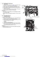
(5) Remove the feed gear and take out the feed motor. (See
Fig13)
Reference:
When attaching the feed motor, the wire has to through the
part
t
of the traverse mechanism assembly. (See Fig.13)
Fig.11
Fig.12
Fig.13
Traverse mechanism assembly
CD servo board
Yellow wire
White wire
Soldered part
q
Soldered part
r
Plate
G
Fixing part
s
Traverse mechanism assembly
Traverse mechanism assembly
Feed gear
Feed motor
part
t
Содержание UX-GB9DABB
Страница 35: ... M E M O ...

