background image

21

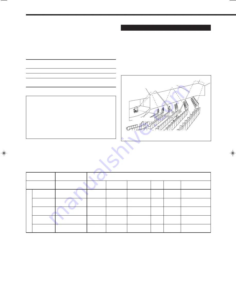
Reproducing the Sound Field

The sound heard in a concert hall or club consists of direct sound
and indirect sound — early reflections and reflections from behind.
Direct sounds reach the listener directly without any reflection. On
the other hand, indirect sounds are delayed by the distances of the
ceiling and walls. These direct sounds and indirect sounds are the
most important elements of the acoustic surround effects.
JVC Theater Surround and DAP modes can create these important
elements, and give you a real “being there” feeling.

Reflections from
behind

Early reflections

DAP modes

In order to reproduce a more acoustic sound field in your listening
room while playing soundtracks of stereo sources, you can use DAP
modes. This mode can be used when the front speakers are
connected to this receiver (without respect to the rear/center
speaker connection).
You can select one of the following to your preference.

LIVE CLUB:

Gives the feeling of a live music club with a low
ceiling.

DANCE CLUB: Gives a throbbing bass beat.

HALL:

Gives clear vocal and the feeling of a concert hall.

PAVILION:

Gives the spacious feeling of a pavilion with a high
ceiling.

Direct sounds

DVD MULTI Playback Mode

This receiver provides the DVD MULTI playback mode for
reproducing the analog discrete 5.1 channel output mode of the
DVD player or other equipment.
You can adjust the DVD MULTI playback mode while playing
back a video software such as a DVD using the analog discrete
5.1 channel output mode.
• For the DVD MULTI playback mode connection, see page 7.
• For details on the DVD MULTI playback mode, see page 27.

BUTTON

SURROUND ON/OFF

                    DSP MODE

MODE

SURROUND ON

THEATER

LIVE CLUB

DANCE CLUB

HALL

PAVILION

DSP OFF

(SURROUND OFF)

ANALOG

V

V

V

V

V

V

V

(2 CH)

(DOLBY PRO LOGIC)

ANALOG

2

2

2

2

2

2

2

(5.1 CH)

(DOLBY PRO LOGIC)

LINEAR PCM

V

V

V

V

V

V

V

(DOLBY PRO LOGIC)

DOLBY DIGITAL

V

 *

1

2

2

2

2

2

V

(DOLBY DIGITAL)

DTS

V

 *

2

2

2

2

2

2

V

(DTS SURROUND)

V

: Possible

2

: Impossible

INPUT

*

1

When 2 channel signal comes in, DOLBY PRO LOGIC is selected. When other signals come in, DOLBY DIGITAL is selected.

*

2

When 2 channel signal comes in, DOLBY PRO LOGIC is selected. When other signals come in, DTS SURROUND is selected.

Available DSP modes according to the input mode

EN20_27.RX-7010V[J]_f

00.12.6, 7:24 PM

21

Содержание RX-7010RBK

Страница 1: ...L SPEAKERS ON OFF DSP MODE PHONES SURROUND ON OFF FM AM TUNING STANDBY POWER FM AM PRESET FM MODE MEMORY INPUT ATT FM AM D I G I T A L D I G I T A L S U R R O U N D DVD MULTI PHONO SOURCE NAME 1 2 COMPULINK Remote CONTROL 2 3 1 5 6 4 8 9 7 P 0 10 10 BASSBOOST EFFECT MENU ENTER TEST REAR L SOUND SUBWOOFER REAR R MUTING CH TVVOL PLAY STOP REW FF VOLUME CA TV DBS CONTROL TV VIDEO REC PAUSE PAUSE RETU...

Страница 2: ...erature accompanying the appliance CAUTION WARNING TO REDUCE THE RISK OF FIRE OR ELECTRIC SHOCK DO NOT EXPOSE THIS APPLIANCE TO RAIN OR MOISTURE CAUTION To reduce the risk of electrical shocks fire etc 1 Do not remove screws covers or cabinet 2 Do not expose this appliance to rain or moisture ATTENTION Afin d éviter tout risque d électrocution d incendie etc 1 Ne pas enlever les vis ni les panneau...

Страница 3: ... and on the user is encouraged to try to correct the interference by one or more of the following measures Reorient or relocate the receiving antenna Increase the separation between the equipment and receiver Connect the equipment into an outlet on a circuit different from that to which the receiver is connected Consult the dealer or an experienced radio TV technician for help For Canada pour le C...

Страница 4: ...ce to Play 10 Adjusting the Volume 11 Selecting the Front Speakers 11 Muting the Sound 12 Reinforcing the Bass 12 Adjusting the Tone 12 Attenuating the Input Signal 12 Adjusting the Subwoofer Output Level 12 Basic Settings 13 Recording a Source 13 Adjusting the Front Speaker Output Balance 13 Changing the Source Name 13 Setting the Subwoofer Information 14 Setting the Speakers for the DSP Modes 14...

Страница 5: ...r operating audio video components 31 37 o TV VOL ume buttons 33 34 VOLUME buttons 11 a Operating buttons for audio video components 31 33 36 37 s CONTROL button 32 33 Front Panel 1 POWER button and STANDBY lamp 10 2 FM AM TUNING 5 buttons 18 3 FM AM PRESET 5 buttons 18 4 FM MODE button 19 5 MEMORY button 18 6 Display 10 7 Remote sensor 9 8 MASTER VOLUME control 11 9 PHONES jack 11 p SURROUND ON O...

Страница 6: ...ation General Be sure your hands are dry Turn the power off to all components Read the manuals supplied with the components you are going to connect Locations Install the receiver in a location that is level and protected from moisture The temperature around the receiver must be between 5 C and 35 C 23 F and 95 F Make sure there is good ventilation around the receiver Poor ventilation could cause ...

Страница 7: ...e following speakers Two pairs of front speakers to produce normal stereo sound One pair of rear speakers to enjoy the surround effect One center speaker to produce more effective surround effect to emphasize human voices One subwoofer to enhance the bass IMPORTANT After connecting the speakers listed above set the speaker setting information properly to obtain the best possible DSP effect For det...

Страница 8: ...ect the following audio video components to this receiver Refer also to the manuals supplied with your components Audio Components Video Components Turntable DVD player CD player TV Cassette deck DBS tuner or CD recorder VCR You can connect these components using the methods described in Analog connections below or in Digital connections see page 8 Analog connections Audio component connections Us...

Страница 9: ...he receiver through the different video terminals you cannot record the picture from the playing component on the recording component In addition if the TV and a playing video component are connected to the receiver through the different video terminals you cannot view the playback picture from the playing component on the TV VCR VCR OUT REC TAPE CDR CD PHONO OUT REC IN PLAY To audio input To audi...

Страница 10: ...dio output To rear left right channel audio output Ï To composite video output DVD player TV To composite video input To S video input To audio output Connect the TV to the MONITOR OUT jack to view the playback picture from the other connected video components When connecting the TV to the AUDIO jacks TV SOUND DBS DO NOT connect the TV s video output to these video input terminals Note When using ...

Страница 11: ...ITAL 4 optical For CD recorder When you want to operate the CD player or CD recorder using the COMPU LINK remote control system connect the target component also as described in Analog connections see page 6 When you want to operate the DVD player using the AV COMPU LINK remote control system connect the DVD player also as described in Analog connections see page 7 Digital output terminal DIGITAL ...

Страница 12: ...lugging the cord always grasp the plug so as not to damage the cord Putting Batteries in the Remote Control Before using the remote control put two supplied batteries first When using the remote control aim the remote control directly at the remote sensor on the receiver 1 On the back of the remote control remove the battery cover 2 Insert batteries Make sure to match the polarity to and to 3 Repl...

Страница 13: ...ct TV sounds or the DBS tuner PHONO Select the turntable CD Select the CD player TAPE CDR Select the cassette deck or the CD recorder FM AM Select an FM or AM broadcast Each time you press the button the band alternates between FM and AM Notes When connecting a CD recorder to the TAPE CDR jacks and a DBS tuner to the TV SOUND DBS jacks change the source name shown on the display For details see pa...

Страница 14: ...or lights up on the display Make sure that the SPK 2 is not on the display To use the speakers connected to the FRONT SPEAKERS 2 terminals press SPEAKERS ON OFF 2 so that the SPK 2 indicator lights up on the display Make sure that the SPK 1 is not on the display To use both sets of the speakers press SPEAKERS ON OFF 1 and 2 so that the SPK 1 and SPK 2 indicators light up on the display To use neit...

Страница 15: ...the bass or treble sound level 10 dB to 10 dB Attenuating the Input Signal When the input level of the playing source is too high the sounds will be distorted If this happens you need to attenuate the input signal level to prevent the sound distortion On the front panel ONLY Press and hold INPUT ATT so that the INPUT ATT indicator lights up on the display Each time you press and hold the button th...

Страница 16: ... repeatedly until L R BALANCE appears on the display The display changes to show the current setting 2 Press CONTROL UP 5 DOWN to adjust the balance Pressing CONTROL UP 5 decreases the left channel output from CNTR Center to 21 Pressing CONTROL DOWN decreases the right channel output from CNTR Center to 21 Changing the Source Name When you have connected a CD recorder to the TAPE CDR jacks or the ...

Страница 17: ...ase or increase in distance Rear delay time for Dolby Digital and DTS Digital Surround is to be set to 5 msec When shipped from the factory delay time is set to 5 msec On the front panel ONLY 1 Press SETTING repeatedly until REAR DELAY appears on the display The display changes to show the current setting Setting the Subwoofer Information Register whether you have connected a subwoofer or not Befo...

Страница 18: ...NG 0dB 10dB CONTROL DOWN UP CONTROL DOWN UP 2 Press CONTROL UP 5 DOWN to select the delay time of the rear speaker output Press CONTROL UP 5 to increase the delay time from 0 msec R_DELAY 0MS to 15 msec R_DELAY 15MS Press CONTROL DOWN to decrease the delay time from 15 msec R_DELAY 15MS to 0 msec R_DELAY 0MS Notes Rear delay time is not valid for the DVD MULTI playback mode You cannot adjust the r...

Страница 19: ...DR as the source name See page 13 Selecting the Analog or Digital Input Mode When you have connected digital source components you need to select the input mode correctly according to the connection you made Before you start remember The digital input DIGITAL IN terminal setting should be correctly done for the sources you want to select the digital input mode for Without setting this digital inpu...

Страница 20: ...ically reset to AUTO To change the input mode back to analog input select ANALOG by pressing INPUT ANALOG DIGITAL again From the remote control 1 Press the source selecting button DVD CD TV DBS or TAPE CDR for which you want to change the input mode Note Among the sources listed above you can select the digital input only for the sources which you have selected the digital input terminals for See ...

Страница 21: ...ore you start remember There is a time limit in doing the following steps If the setting is canceled before you finish start from step 1 again On the front panel ONLY 1 Tune in the station you want to preset see Tuning in Stations Manually If you want to store the FM reception mode for this station select the FM reception mode you want See Selecting the FM Reception Mode on page 19 2 Press MEMORY ...

Страница 22: ...FM stereo broadcast is hard to receive or noisy You can change the FM reception mode while receiving an FM broadcast You can store the FM reception mode for each preset station Press FM MODE on the front panel or on the remote control Each time you press the button the FM reception mode alternates between AUTO and MONO L SPK AUTOMUTING TUNED STEREO ANALOG 1 R L SPK TUNED ANALOG 1 R AUTO When a pro...

Страница 23: ...ter In addition Dolby Digital enables stereo rear sounds and sets the cutoff frequency of the rear treble at 20 kHz compared to 7 kHz for Dolby Pro Logic These facts enhance the sound movement and being there feelings much more than Dolby Pro Logic To enjoy the software encoded with Dolby Digital you must connect the source component using the digital terminal on the rear of this receiver See page...

Страница 24: ...bbing bass beat HALL Gives clear vocal and the feeling of a concert hall PAVILION Gives the spacious feeling of a pavilion with a high ceiling Direct sounds DVD MULTI Playback Mode This receiver provides the DVD MULTI playback mode for reproducing the analog discrete 5 1 channel output mode of the DVD player or other equipment You can adjust the DVD MULTI playback mode while playing back a video s...

Страница 25: ...aker Rear speaker Front speaker TV Center speaker Front speaker By pressing SURROUND ON OFF the surround mode turns on and off SURROUND ON PRO LOGIC DOLBY DIGITAL or DTS SURROUND SURROUND OFF DSP mode is canceled By pressing DSP MODE the DSP modes change as follows THEATER LIVE CLUB DANCE CLUB HALL PAVILION DSP OFF DSP mode is canceled By pressing SURROUND ON OFF the surround mode turns on and off...

Страница 26: ... page 14 5 Adjust the speaker output levels To adjust the center speaker level press CENTER from 10 dB to 10 dB To adjust the left rear speaker level press REAR L from 10 dB to 10 dB To adjust the right rear speaker level press REAR R from 10 dB to 10 dB 6 Press TEST again to stop the test tone On the front panel You can also use the buttons on the front panel to adjust the Surround modes However ...

Страница 27: ... DSP EFFECT 2 DSP EFFECT 3 DSP EFFECT 4 DSP EFFECT 5 SOUND 4 TEST 1 EFFECT 4 TEST DSP MODE DSP MODE 2 3 MENU CENTER 5 6 ENTER REAR L 8 9 ENTER REAR R ADJUST SETTING 5 Press TEST again to stop the test tone 6 Press EFFECT to select an effect level you want Each time you press the button the effect level changes as follows As the number increases JVC Theater Surround becomes stronger normally set it...

Страница 28: ...JUST repeatedly until DSP EFFECT appears on the display The display changes to show the current setting 2 Press CONTROL UP 5 DOWN to select the effect level Each time you press the button the effect level changes as follows As the number increases the selected DAP mode becomes stronger normally set it to DSP EFFECT 3 From the remote control 1 Press DSP MODE repeatedly until the DAP mode LIVE CLUB ...

Страница 29: ...S Digital Surround and labeled with mark To cancel the Dolby DTS Surround mode Press SURROUND ON OFF again SURROUND OFF appears on the display For the other DSP modes 1 Press DSP MODE repeatedly until the mode you want appears on the display Each time you press the button the DSP modes change See page 22 for more details 2 Select and play a sound source To enjoy JVC Theater Surround play back a so...

Страница 30: ...ment go to the following steps 3 Adjust the speaker output levels 1 Press ADJUST repeatedly until one of the following indications appears on the display CENTER LEVEL To adjust the center speaker level REAR L LEVEL To adjust the left rear speaker level REAR R LEVEL To adjust the right rear speaker level 2 Press CONTROL UP 5 DOWN to adjust the selected speaker output level from 10 dB to 10 dB 3 Rep...

Страница 31: ...ote control the receiver automatically turns on and changes the source to the component On the other hand if you select a new source on the receiver or on the remote control the selected component begins playing immediately In both cases the previously selected source continues playing without sound for a few seconds Automatic Power On Off Standby only possible with the COMPU LINK 3 and COMPU LINK...

Страница 32: ...nals TV VIDEO VCR OUT REC IN PLAY MONITOR OUT DVD DBS DVD VHS VCR TV To Video input 2 DVD player DO NOT use these video terminals VCR DVD player TV AV COMPU LINK AV COMPU LINK VHS AV COMPU LINK DVD AV COMPU LINK AV COMPU LINK terminal on the rear panel Notes When connecting only the VCR and DVD player to this receiver connect it directly to the receiver using cable with the monaural mini plugs You...

Страница 33: ...DVD MULTI the TV and DVD player will turn on automatically When you turn off the receiver the TV VCR and the DVD player will turn off Note If you turn off the receiver while recording on the VCR the VCR will not turn off but continue recording 1 If you have already plugged your VCR DVD player TV and this receiver into the AC outlets unplug their AC power cords first 2 Connect your VCR DVD player T...

Страница 34: ...er 30 press 10 10 then 10 Operating JVC s Audio Video Components You can operate JVC s audio and video components with this receiver s remote control since control signals for JVC components are preset in the remote control Operating Audio Components IMPORTANT To operate JVC s audio components using this remote control You need to connect JVC audio components through the COMPU LINK SYNCHRO jacks s...

Страница 35: ...s 3 then 0 2 then 3 Selecting disc number 10 track number 5 and starting playback Press 1 0 then 0 5 then 3 Selecting disc number 105 track number 12 and starting playback Press 1 0 5 then 1 2 then 3 Turntable After pressing PHONO you can perform the following operations on a turntable PLAY3 Starts playing STOP7 Stops operations Cassette deck After pressing TAPE CDR or CONTROL repeatedly until TAP...

Страница 36: ... the TV TV VOL Adjusts the volume TV VIDEO Sets the input mode either TV or VIDEO After pressing TV DBS you can perform the following operations on a TV CH Changes the channels 1 9 0 100 Selects the channels RETURN Alternates between the previously selected channel and the current channel Operating Video Components IMPORTANT To operate JVC s video components using this remote control You need to c...

Страница 37: ...els The 10 button will function as the ENTER button if your TV requires pressing ENTER after selecting a channel number Note Refer to the manual supplied with your TV 5 Try to operate your TV by pressing TV POWER When your TV turns on or off you have entered the correct code If there are more than one code listed for your brand of TV try each one until the correct one is entered This remote contro...

Страница 38: ...t code If there are more than one code listed for your brand of CATV converter or DBS tuner try each one until the correct one is entered Note You cannot use both the CATV converter and DBS tuner at the same time Manufacturer Codes GENERAL INSTRUMENT 06 07 08 09 10 11 12 13 14 29 HAMLIN REGAL 01 02 03 04 05 JERROLD 06 07 08 09 10 11 12 13 14 OAK 15 16 17 PANASONIC 18 19 20 PIONEER 21 22 SCIENTIFIC...

Страница 39: ...acturer s VCR 1 Press and hold VCR POWER 2 Press VCR 3 Enter manufacturer s code using buttons 1 9 and 0 See the list to the right to find the code 4 Release VCR POWER The following button can be used for operating the VCR VCR POWER Turns on and off the VCR After pressing VCR you can perform the following operations on the VCR CH Changes the TV channels on the VCR 1 10 0 100 10 Selects the TV chan...

Страница 40: ...DVD MULTI you can perform the following operations on a DVD player PLAY3 Starts playing 4 Returns to the beginning of the current or previous tracks Skips to the beginning of the next track STOP7 Stops playing PAUSE8 Stops playing temporarily To release it press PLAY After pressing DVD or DVD MULTI these buttons can be used for the DVD menu operations Note For detailed menu operations refer to the...

Страница 41: ...onsult your dealer Remove the obstruction Replace batteries Select the correct remote control operation mode See page 31 PROBLEM The display does not light up No sound from speakers Sound from one speaker only Continuous hiss or buzzing during FM reception Occasional cracking noise during FM reception Howling during record playing Noise is heard OVERLOAD starts flashing on the display DSP MICON NG...

Страница 42: ...660 nm 30 nm Corresponding to Linear PCM Dolby Digital and DTS Digital Surround with sampling frequency 32 kHz 44 1 kHz 48 kHz Audio Output Level TAPE CDR VCR 220 mV Digital output Optical DIGITAL OUTPUT Signal wave length 660 nm Output level 21 dBm to 15 dBm Signal to Noise Ratio 66 IHF 78 IHF PHONO MM 70 dB 78 dB at REC OUT CD TAPE CDR TV SOUND DBS VCR DVD 87 dB 67 dB Frequency Response 8 Ω PHON...

Страница 43: ...1 kHz Stereo Separation at REC OUT 35 dB at 1 kHz Alternate Channel Selectivity 45 dB 400 kHz Frequency Response 30 Hz to 15 kHz 0 5 dB 3 dB AM tuner Tuning Range 530 kHz to 1 710 kHz Usable Sensitivity Loop antenna 400 µV m Signal to Noise Ratio 50 dB 100 mV m General Power Requirements AC 120V 60 Hz Power Consumption 180 W 230 VA at operation 2 W in standby mode Dimensions W x H x D 435 mm x 146...

Страница 44: ...E CENTER LOCATIONS 10 New Maple Avenue Pine Brook NJ 07058 9641 973 396 1000 5665 Corporate Avenue Cypress CA 90630 0024 714 229 8011 13 Cummings Park Woburn MA 01801 781 376 9100 705 Enterprise Street Aurora IL 60504 8149 630 851 7855 10700 Hammerly Suite 110 Houston TX 77043 713 935 9331 890 Dubuque Avenue South San Francisco CA 94080 1804 650 871 2666 1500 Lakes Parkway Lawrenceville GA 30243 5...

Страница 45: ... attachment not provided with the products or if the model number or serial number has been altered tampered with defaced or removed 2 Initial installation and installation and removal for repair 3 Operational adjustments covered in the Owner s Manual normal maintenance video and audio head cleaning 4 Damage that occurs in shipment due to act of God and cosmetic damage 5 Signal reception problems ...

Страница 46: ...VICTOR COMPANY OF JAPAN LIMITED EN 0101NHMMDWJEIN J VC ...

Отзывы: