2-2
2.2
ADJUSTMENT MODE
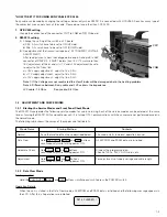
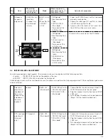
Adjust the power supply of the RM-P210 by using the Adjustment mode (menu).
2.2.1
Procedures
(1) Starting the Adjustment mode
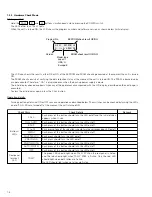
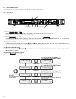
Hold the MENU , F3 and F4 buttons simultaneously while pressing the POWER switch ON.
All of the front panel LEDs light in the Adjustment mode.
(2) Selecting the adjustment item
Turn the SHUTTER potentiometer to select a menu item, and then press the SHUTTER potentiometer. The “
→
“ cursor moves
to the adjustment value area, indicating that the adjustment is ready.
(3) Adjustment method
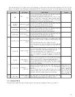
After selecting the adjustment item, turn the SHUTTER potentiometer again to adjust the value. See the description of each
adjustment item for details. Note that “4. LENGTH” is not used in the adjustments.
(4) Saving the adjustment data
After adjustment, press the SHUTTER potentiometer to save the adjusted data. The display returns to the adjustment item
selection menu in step (2).
(5) Exiting from the Adjustment mode
Press the POWER switch to OFF.
→
1 . VOL T ADJ 1
1
5
5
V
0
→
2 . VOL T ADJ 1
1
7
7
V
0
→
3 . VOL T ADJ 1
1
9
9
V
0
→
4 . LENGTH
1
2
5
0
V
M
1 . VOL T ADJ
→
1
1
5
5
V
0
2 . VOL T ADJ
→
1
1
7
7
V
0
3 . VOL T ADJ
→
1
1
9
9
V
0
4 . LENGTH
→
2 0M
Turn SHUTTER to adjust the voltage to 15 V.
(“150” shown below is an example of display.)
Turn SHUTTER to adjust the voltage to 17 V.
(“170” shown below is an example of display.)
Turn clockwise to move
downward.
Turn counterclockwise
to move upward.
Turn SHUTTER to adjust the voltage to 19 V.
(“190” shown below is an example of display.)
Turn SHUTTER to vary LENGTH then adjust
VR on the PCB.
SHUTTER
push
Saves data.
Saves data.
Saves data.
SHUTTER
push
SHUTTER
SHUTTER
push
SHUTTER
push
CALL
TALLY
INTERCOM
LEVEL
FULL AUTO
F1
SHUTTER
GAIN
F2
F3
MENU/SHUTTER
GAIN
PAINT
AUTO
B
R
W.BAL
AUTO
MANU
WHITE
MASTER BLACK
POWER
I
O
IRIS
STEP
SHUTTER
MENU
PUSH-ON
DOWN
UP
VARIABLE
PUSH-ON
HIGH
LOW
B
A
PRESET
CLOSE
OPEN
MID
DOWN
UP
F4
BARS
REMOTE CONTROL UNIT RM-P210
(1)
(1)
(1)
LCD Display
(1), (5)
(2),(3),(4)


