2-1
2.1
INSTRUMENTS REQUIRED FOR ADJUSTMENTS, THEIR SETUPS
2.1.1
Instruments to be Prepared
(1) Color video camera: GY-DV550, KY-D29, KY-D29W, KY-27C or KY-19 (With the KY series camera, a KA-27 camera adapter is an
additional requirement.)
(2) Camera cable: VC-P112 (20 m)
(Always use a 20-meter cable. Correct adjustment is not possible with other cable lengths.)
(3) Color monitor TV
(4) Digital voltmeter (input impedance 10 M
Ω
or more)
(5) Oscilloscope (2-trace scope)
(6) 75
Ω
termination resistance
(7) Headset: KA-310U or a headset with 200
Ω
to 600
Ω
impedance at 1 kHz
(8) IN MEGA CYCLE Chart (Part No. RESC-014)
(9) Camera Extension Board (Part No. SCK2164) ...... (Required when the connected camera model is the KY-29 or the KY-D29W.)
2.1.2
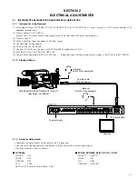
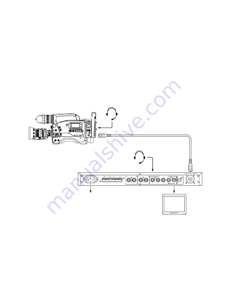
Standard Setup
SECTION 2
ELECTRICAL ADJUSTMENTS
2.1.3
Setup for Adjustments
• Complete the adjustments of the camera itself in advance.
• Use the same lighting and other conditions as those used in the camera adjustments.
• Set the camera switches as follows.
䡵
GY-DV550
POWER
: RM
MODE
: RM
OPERATE : RM
VTR
: STBY
26 PIN OUT in Camera Setup Menu : RGB
䡵
KY-D29, KY-D29W, KY-27C, KY-19 + KA-27
POWER
: RM/VTR
MODE
: RM
SIG
: RGB
OPERATE : ON/ST-BY
H
G
C
C
PVW
PGM
TALLY
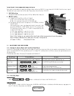
AC~IN AC100V 50V/60Hz
INTERCOM
AUX VIDEO INPUT
GENLOCK INPUT
VIDEO OUTPUT
Y/C OUT
CAMERA CABLE
R/R-Y
B/B-Y
COMPOSITE VIDEO
G/Y
Camera cable
VC-P112 (20 m)
Intercom
KA-310U or equivalent
Intercom
KA-310U or equivalent
Monitor
To poer supply
75
Ω
termination
GY-DV550/KY-D29/KY-D29W/KY-27C/KY-19
(Illustration: GY-DV550)
RM-P210
SHUTTER STATUS
MENU
FILTER
3200k
1
5600k+1/8ND
2
5600k+1/64ND
3
ALARM
MONITOR
OPERATE
NG
GAIN
OUTPUT W
HT.BAL
VTR
ON
OFF
AUTO IRIS
LOLUX
BACK L
NORMAL
SPOT L
STRETCH
NORMAL
COMPRESS
LIGHT
ON
OFF
COUNTER
AUDIO SELECT
MANUAL
AUTO
CH-1
CH-2
CH-1
CH-2
REAR
FRONT
RM
AUDIO INPUT
MODE
CTL
TC
UB
CH-1
MIX
CH-2
RESET
OPERATE/WARNING
MONITOR
SELECT
CH-1 AUDIO
LEVEL
CH-2
VTR
ON
OFF
INCOM
MIC
INCOM
MIC
LEVEL
POWER
OFF
RM
DC IN
/BATT.
CALL
CARBON
DYNAMIC
FULL AUTO
BLACK


