RC-W305
7
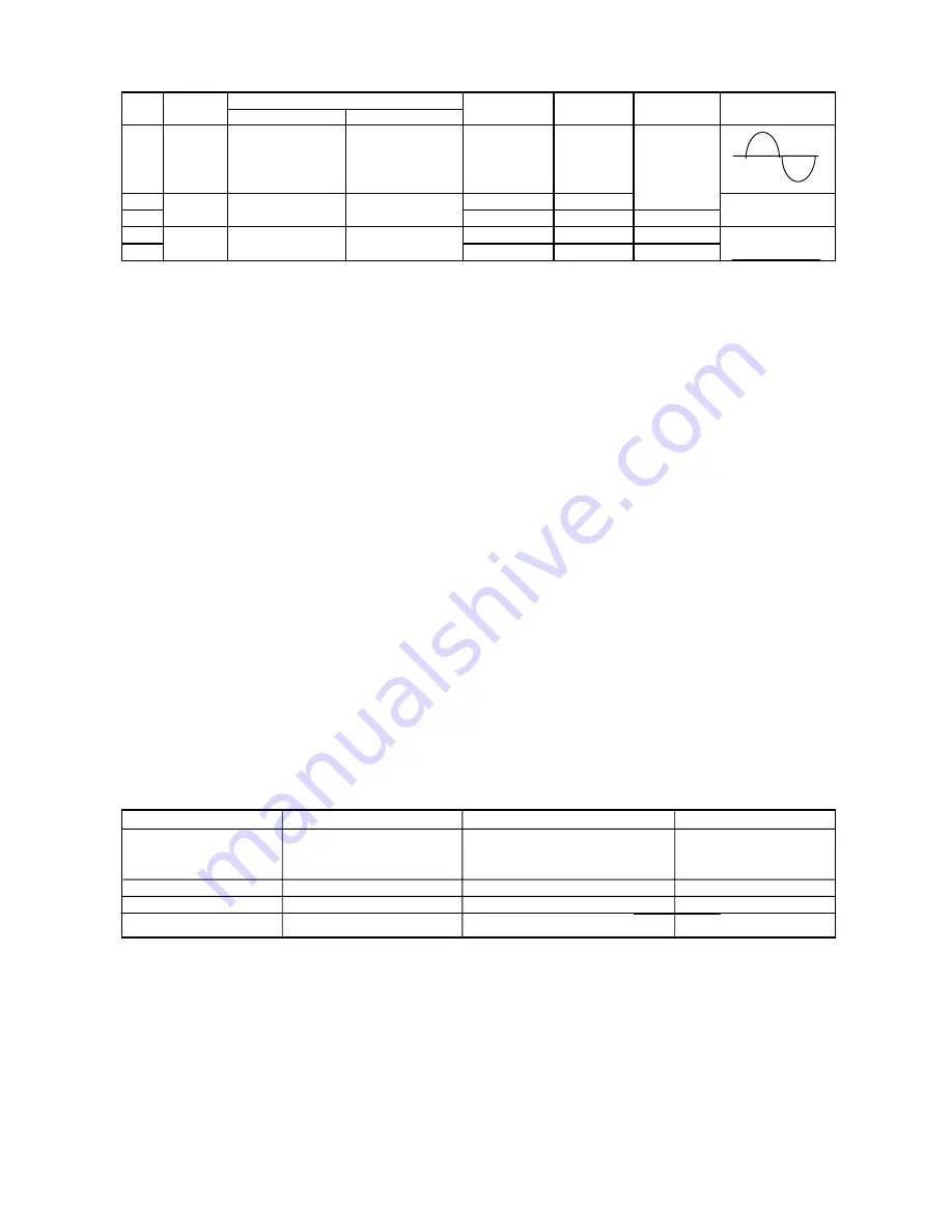
e. FM Adjustment
Band switch : FM
FM Dummy antenna : 75 ohms unbalance
Adjusting Connection
position of
VTVM
Circuit
Input
Output
tuning dial
Oscilloscope
Connect sweep
1
IF
generator to IC101
10.7 MHz
Low
T101
~
T103
(18)PIN(A)
2
Tuning
Connect FM SG to
Connect VTVM to
87.4 MHz
Low end
L103
3
coverage
FM ANT & D105(-)
speaker terminals.
108.4 MHz
High end
PVC101-C1
4
Connect FM SG to
Connect VTVM to
90.0 MHz
90.0 MHz
L102
5
FM ANT &D105(-)
speaker terminals.
106.0 MHz
106.0 MHz
PVC101-C2
偩
.TAPE DECK ADJUSTMENTS
1. HEAD REPLACEMENT
After replacement, demagnetize. the heads by using a degausser.
Be sure to clean the head before attempting to make any adjustments.
All wiring should be returned to the original position after work is completed.
2. HEAD AZIMUTH ADJUSTMENT
(1) Load the test tape(VTT-703, etc., 10 KHZ) for azimuth
adjustment.
(2) Press the PLAY button.
(3) Use a cross-tip screwdriver to turn the screw for azimuth
adjustment so that the left and right output are maximized
(4) Press the STOP button.
(5) After completion of the adjustment, use thread lock(TB-1401B)
to secure the azimuth-adjustment screw.
3. MOTOR SPEED ADJUSTMENT
(1) Insert the test tape(MTT-111N, etc., 3,000 HZ)
(2) Press the PLAY button.
(3) Use a flat-tip screwdriver to turn the SVR(located inside the
rear of the motor) to adjust SVR so that the frequency counter
become 3,000 HZ
4. CHECKING THE MECHANISM TORQUSE AND TENSION
Clean the head, capstan and pinch roller making any measurement.
Measurement
Take-up torqe
Back tension
Tape tension
Drive-power cassette
Cassette ofr PLAY:TW-211A
PLAY: TW-2111A
measurement F.FWD/REW:TW-2231
TW-2412
PLAY
30-60 gr.cm
2.0 - 4.5 gr. cm
60 gr or more
F.FWD
55-120 gr.cm
------
------
REW
55-120 gr.cm
------
------
Step
SG Frequency
Tracking
Max.
Max.
Adjustment
Connect sweep
generator to
IC101(24)pin (B)
Содержание RC-W305
Страница 8: ...XL SV320SL SV305GD XL SV308BU 8 RC W305 LA1824 Block Diagram Description of Major IC ...
Страница 9: ...RC W305 9 BA3308 Block Diagram ...
Страница 10: ...XL SV320SL SV305GD XL SV308BU 10 RC W305 Block Diagram BA3416BL ...
Страница 11: ...RC W305 11 ...
Страница 13: ...RC W305 13 Wiring Connections Diagram ...
Страница 14: ...XL SV320SL SV305GD XL SV308BU 14 RC W305 Schematic Diagram ...
Страница 15: ...RC W305 15 Printed Circuit Board ...
Страница 16: ...XL SV320SL SV305GD XL SV308BU 16 RC W305 ...
Страница 17: ...RC W305 17 ...
Страница 18: ...JVC Asia Pte Ltd 101 Thomson Road 28 04 United Squares Singapore 307591 No 28223 Printed in Singapore 200505 L ...


