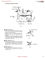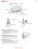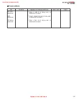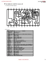
1-9
RC-BZ5LB/BZ5RD
RC-BZ6BU
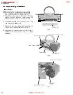
Prior to performing the following procedure, remove
the CD / cassette and amplifier assembly.
Disconnect the harness from connector CN704 on
the key switch / display board (The harness is
extending from the door switch board).
Press EJECT button to open the CD door.
Remove the two screws D on the front of the CD
cover and door unit.
Raise the front part of the CD cover and door unit
and detach upward. Then push the whole unit
backward until it comes off.
1.
2.
3.
4.
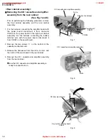
Removing the CD cover and door unit
(See Fig.9 and 10)
Prior to performing the following procedure, remove
the CD cover and door unit.
Turn over the CD cover and door unit and gently
spread apart the locking tab. Then remove the CD
door switch board in the direction of the arrow while
releasing it from joint d.
1.
Removing the CD door switch board
(See Fig.11)
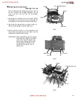
Prior to performing the following procedure, remove
the front cabinet assembly and the rear cabinet
assembly.
Disconnect the card wires from connector CN701,
CN702 and CN703, then the harness from CN704
on the key switch / display board.
Remove the four screws E attaching the key switch /
display board.
The key switch / display board can be removed
even if the mechanism cover is attached.
1.
2.
Removing the key switch / display board
(See Fig.12)
At this point, the CD mechanism unit
will become removable. So handle the
rear cabinet with care.
ATTENTION:
CD cover and door unit
Fig.10
Fig.11
Fig.12
Tab
Joint d
CD door switch board
Key switch / display board
Key switch / display board
CN702(RC-BZ5 only)
CN704
CN703
CN701
E
E
Cassette mechanism assembly
www.freeservicemanuals.info
11/28/2017
Digitized in Heiloo Netherlands


