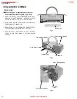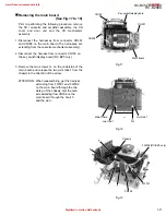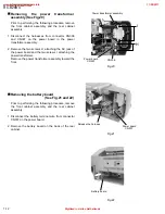
1-8
RC-BZ5LB/BZ5RD
RC-BZ6BU
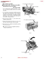
Prior to performing the following procedure, remove
the front cabinet assembly and the rear cabinet
assembly.
For the harness connecting the amplifier board with
the power board, disconnect it from connector
CN306 on the power board in the right rear cabinet
assembly. For the harness connecting the battery
terminal wire with the power board, disconnect it
from CN307 on the power board.
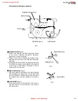
Remove the two screws C on the bottom of the
cassette mechanism unit.
Release the harnesses from the slot a, b and c and
the notch of the main board in the rear cabinet.
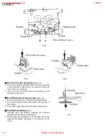
Remove the CD / cassette and amplifier assembly
from the rear cabinet.
Now the CD / cassette and amplifier assembly is
ready to conduct burn-in.
1.
2.
3.
4.
Removing the CD / cassette and amplifier
assembly from the rear cabinet
(See Fig.7 and 8)
<Rear cabinet assembly>
CD / cassette and amplifier assembly
Slot a
Slot c
Power board
CN307
CN306
Fig.7
Fig.8
Fig.9
CD / cassette and amplifier assembly
Slot b
D
Key switch / display board
CN704
CD door eject button
Release the hornese
C
www.freeservicemanuals.info
11/28/2017
Digitized in Heiloo Netherlands


