E24
CAUTION
Setting the dip switches
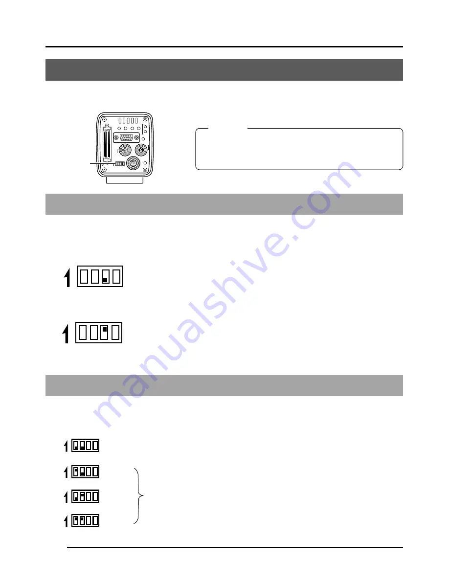
The type of PC monitor to use and the ID during SCSI connection are set using the dip switches.
Monitor output settings
Dip switch no. 3 is set depending on whether using a system which uses a commercially avail-
able VGA monitor or a system which uses a capture board. <Default setting: OFF>
VGA output setting
Set when directly connecting a VGA monitor to the MONITOR ter-
minal on the rear of the main unit.
SXGA output setting
Set for systems using a capture board.
The signal from the MONITOR terminal on the rear of the main unit
is inputted through the analog input compatible video capture board.
(
Page 68 Capturing images using the image capture board)
SCSI ID settings
DiP switches 1 and 2 are set depending on the used system to set the SCSI ID. <Default ID: 7>
Set when connecting a printer or MO drive unit directly to the main
unit. When making this setting, the main unit will become the initia-
tor.
Set when exporting images to a PC.
Make sure that the ID numbers of the connecting devices are not
the same.
When making this setting, the PC will become the initiator and the
main unit will become the target.
(
Page 66 Connecting to a PC)
Turn the power off before setting the dip switches. Setting
the switches with the power on will not change the set-
tings.
3. Settings and adjustments for recording
SEE INSTRUCTION MANUAL
POWER
DC IN
REMOTE
MONITOR
LENS
FREEZE
PLAY
SET
DOWN
AW/SEL
SEND
SCSI
UP
MENU
MODE
REC
ON 1 2 3 4
ON 1 2 3 4
ON 1 2 3 4
ON 1 2 3 4
ON 1 2 3 4
ON 1 2 3 4
ON 1 2 3 4
ID=7
ID=6
ID=5
ID=4
Dip switches
Set to OFF
Set to ON


