


Revised in August 1998
7
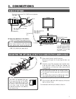
Pin No.
Signal
Pin No.
Signal
1
2
3
4
5
6
SERVO SELECT(F)
SERVO SELECT(Z)
GND
IRIS C/L
IRIS CTL
12V
7
8
9
10
11
12
COM
FOCUS CTL
ZOOM CTL
SERVO SELECT(I)
COM (+V)
COM (–V)
View from the rear of the KY-F58
(12-pin connector, female)
9
8
7
6
1
10
12
11
2
3
4
5
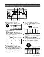
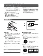
2. CONTROLS, INDICATIONS AND CONNECTORS (Cont’d)
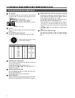
CAMERA CONTROL [Rear side] (Cont’d)
25
[RS-232C] Communication port (D-Sub 9Pin)
Connect to an RS-232C interface in a personal computer
or other control unit.
Use a cross cable for connection.
26
[AC INPUT] AC Power connector
It connects with a provided AC cable to a standard AC120V
electric outlet.
[SIGNAL EARTH] signal ground terminal
This is not a ground for safety from electrical shock. It is a
GND for signals among units.
[LENS REMOTE] lens remote control connector
It connects to the lens remote control unit (optional).
Refer to the “SYSTEM APPLICATION” on page 11.
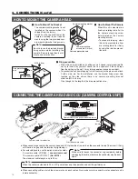
RGB/COMPONENT
Y/C
VIDEO
HD/VBS
FREEZE
VD
WEN
FLASH
OUTPUT
EXT REF
EXT TRIGGER
RS-232C
LENS
REMOTE
SEE INSTRUCTION MANUAL
AC- INPUT
28
29
30
31
27
26
25
24
23
22
20
21
SIGNAL
EARTH
Pin No.
Detail
Pin No.
Detail
1
2
3
4
5
NC
RxD
TxD
DTR
GND
6
7
8
9
DSR
RTS
CTS
NC
1
6
5
9
View from the rear of the KY-F58
(9-pin connector, male)
20
[Y/C] Y/C output signal connector (4 Pin)
This connector outputs Y/C separated video signal.
21
[RGB/COMPONENT] RGB/Component output connector
(9Pin)
This is the RGB/Component signal output connector.
To switch between the RGB and the COMPONENT on the
MENU screen.
Refer to the “TOTAL SETTING SCREEN” on page 25.
22
[VIDEO] Video output connector (BNC)
This is the composite video signal output connector.
23
[HD/VBS] HD/VBS sync signal input connector (BNC)
This connector inputs HD (Horizontal sync signal) or VBS
(Composite video signal) to synchronize the unit.
Refer to the “SYSTEM APPLICATION” on page 11.
24
[VD] VD sync signal input connector (BNC)
This connector inputs VD (vertical sync signal) to synchro-
nize the unit.,
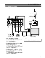
Pin No.
1
2
3
4
4
2
3
1
GND (ground)
GND (ground)
Luminance (Y, 1 V(p-p), 75-ohm)
Chroma signal
(C, 0.286 V (p-p), 75-ohm) [U Ver.]
(C, 0.3 V (p-p), 75-ohm) [E Ver.]
Signal
View from the rear
of the KY-F58
(4-pin connector, female)
Pin No.
Signal
Pin No.
Signal
1
2
3
4
5
GND
GND
R/R-Y
G/Y
B/B-Y
6
7
8
9
VBS
SYNC
GND
GND
5
9
1
6
View from the rear of the KY-F58
(9-pin connector, female)


