background image

1-22 (No.MA454<Rev.001>)

4.8.3 Error codes of panel mechanism

Detail

Error code

(Service mode)

 Open error
1. Time out error by OPEN position cannot detect.

0A0001

Close error (ANGLE 1 error)
1. Time out error by ANGLE 1 position cannot detect.

0B0006

Angle positioning error
Moving to 10 degrees (ANGLE 2 error)
1. Time out error by ANGLE 2 position cannot detect at moving to open position.
2. Missing to ANGLE 1 and detected ANGLE 2 position at moving to open position.
3. Time out error by ANGLE 2 cannot detect at moving close position.

0D0021
0D0022
0D0023

Moving to 20 degrees (ANGLE 3 error)
1. Time out error by ANGLE 3 position cannot detect at moving to open position.
2. Missing to ANGLE 2 and detected ANGLE 3 position at moving to open position.
3. Time out error by ANGLE 3 cannot detect at moving close position.

0E0031
0E0032
0E0033

Moving to 30 degrees (ANGLE 4 error)
1. Time out error by ANGLE 4 position cannot detect at moving to open position.
2. Missing to ANGLE 3 and detected ANGLE 4 position at moving to open position.
3. Time out error by ANGLE 4 cannot detect at moving close position.

0F0041
0F0042
0F0043

Abnormal switch position at moving panel
The Panel move to open and close position, detected abnormal switch position.

0A0000

OPEN

1

Panel

Close

Main body

2

3

4

PANEL ANGLE

Open

30 degrees

20 degrees

10 degrees

Содержание KD-AVX55A

Страница 1: ...EE KD AVX77A COPYRIGHT 2009 Victor Company of Japan Limited Lead free solder used in the board material Sn Ag Cu melting point 219 Centigrade Lead free solder used in the board material Sn Cu melting point 230 Centigrade TABLE OF CONTENTS 1 PRECAUTION 1 5 2 SPECIFIC SERVICE INSTRUCTIONS 1 8 3 DISASSEMBLY 1 9 4 ADJUSTMENT 1 16 5 TROUBLESHOOTING 1 28 Only for KD AVX77 Only for KD AVX77J Except KD AV...

Страница 2: ...Hz AM with channel interval set to 10 kHz 530 kHz to 1 710 kHz with channel interval set to 9 kHz 531 kHz to 1 602 kHz FM Tuner Usable Sensitivity 9 3 dBf 0 8 µV 75 Ω 50 dB Quieting Sensitivity 16 3 dBf 1 8 µV 75 Ω Alternate Channel Selectivity 400 kHz 65 dB Frequency Response 40 Hz to 15 000 Hz Stereo Separation 40 dB AM Tuner Sensitivity Selectivity 20 µV 40 dB DVD CD Signal Detection System Non...

Страница 3: ...2 Mass approx 2 2 kg 4 9 lbs excluding the accessories AMPLIFIER Maximum Power Output Front Rear 50 W per channel Continuous Power Output RMS Front Rear 20 W per channel into 4 Ω 40 Hz to 20 000 Hz at no more than 0 8 total harmonic distortion Load Impedance 4 Ω 4 Ω to 8 Ω allowance Equalizer Control Range Frequencies 60 Hz 150 Hz 400 Hz 1 kHz 2 5 kHz 6 3 kHz 15 kHz Level 10 dB Signal to Noise Rat...

Страница 4: ...y Version Bluetooth 1 2 certified Output Power 4 dBm Max Power class 2 Service Area Within 10 m Profile HFP Hands Free Profile 1 5 OPP Object Push Profile 1 1 A2DP Advanced Audio Distribution Profile 1 2 AVRCP Audio Video Remote Control Profile 1 3 MONITOR Screen Size 5 4 inch wide liquid crystal display Number of Pixel 576 000 pixels 800 horizontal 3 RGB 240 vertical Drive Method TFT Thin Film Tr...

Страница 5: ...ne jack control shafts etc to be sure the product is safe to operate without danger of electrical shock Do not use a line isolation transformer during this check Plug the AC line cord directly into the AC outlet Using a Leakage Current Tester measure the leakage current from each exposed metal parts of the cabinet particular ly any exposed metal part having a return path to the chassis to a known ...

Страница 6: ...eck the condition of the laser diode in the optical pickup The tester s internal power source can easily destroy the laser diode 1 6 Handling the traverse unit optical pickup 1 Do not subject the traverse unit optical pickup to strong shocks as it is a sensitive complex unit 2 Cut off the shorted part of the flexible cable using nippers etc after replacing the optical pickup For specific details r...

Страница 7: ...oduct uses visible and or invisible laser radiation and is equipped with safety switches which prevent emission of radiation when the drawer is open and the safety interlocks have failed or are defeated It is dangerous to defeat the safety switches 5 CAUTION If safety switches malfunction the laser is able to function 6 CAUTION Use of controls adjustments or performance of procedures other than th...

Страница 8: ...1 8 No MA454 Rev 001 SECTION 2 SPECIFIC SERVICE INSTRUCTIONS This service manual does not describe SPECIFIC SERVICE INSTRUCTIONS ...

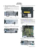
Страница 9: ... three screws E attaching the Top chassis See Fig 3 Fig 3 5 Remove the two screws F attaching the Top chassis See Fig 4 Fig 4 3 1 2 Removing the Main board See Fig 5 to 10 1 Disconnect the card wire from Front chassis connected to connector CN962 of the Main board See Fig 5 2 Disconnect the connector wire from Gear bracket unit con nected to connector CN881 and CN891 of the Main board See Fig 5 3 ...

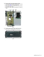
Страница 10: ...ig 8 Fig 8 7 Remove the two screws K attaching the Heat sink See Fig 9 8 Remove the one screw L attaching the Antenna wire See Fig 9 9 Remove the one screw M attaching the USB cable See Fig 9 Fig 9 10 Remove the one screw N attaching the Main board See Fig 10 Fig 10 3 1 3 Removing the DVD mechanism See Fig 11 1 Remove the three screws P attaching the DVD mecha nism Fig 11 J CN981 CN861 CN871 CN823...

Страница 11: ... to connector CN395 of the Connection board 2 Disconnect the connector wire from BT antenna connected to connector of RF module 3 Remove the three screws Q attaching the Connection board Fig 12 3 1 5 Removing the Panel A control board See Fig 13 1 Remove the six screws R attaching the Rear cover Fig 13 Connector CN395 Q Q R R ...

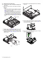
Страница 12: ...ection the flexible wire to the connector CN101 on the Front end board Fig 1 2 Voltage supply to TP79 and TP81 approx DC 3 0V until Clamper is shift to loading complete position See Fig 2 3 Disconnect the flexible wires fromTraverse mechanism assembly connected to connector CN101 and CN164 of the Front end board See Fig 2 Fig 2 4 Remove the five screws A attaching the Top cover assembly See Fig 3 ...

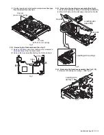
Страница 13: ... the two screws B attaching the Front end board Fig 7 3 2 3 Removing the Loading arm assembly See Fig 8 1 Remove the Loading arm spring L from Loading arm assembly 2 Slide to left side and then disengage hook a then hook b Fig 8 3 2 4 Removing the Gear base assembly See Fig 9 10 1 Remove the Loading arm spring L See Fig 9 Fig 9 Dumper same color spring Dumper Different color spring B B TP79 TP81 L...

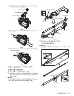
Страница 14: ...he Slide cam assembly See Fig 13 1 Slide to backward the Slide cam assembly and the remove the Slide cam spring 2 Slide to frontward the slide cam assembly and then take out it Fig 13 3 2 8 Removing the Photo board See Fig 14 1 Pressing the hook c and then slide to backward slide to the arrow side the Disc plate 2 Remove the one screw F attaching the Photo board Fig 14 3 2 9 Removing the Loading m...

Страница 15: ...assembly 5 Lift up the part b of the Roller assembly and then release part c When release part c R collar R is easy to come off does not lose it CAUTION When reattach the Roller assembly Middle gear should keep direction and Slit washer should be change new part Fig 19 3 2 11 Removing the Roller See Fig 20 1 Remove the Slit washer 2 Pull out the Roller shaft CAUTION When reattach the Roller shaft ...

Страница 16: ...ndication 0 Loudness OFF 4 4 Dummy load Exclusive dummy load should be used for AM and FM For FM dummy load there is a loss of 6dB between SSG output and antenna input The loss of 6dB need not be considered sincedirect reading of figures are applied in this working standard 4 5 How to connect the extension cable for adjusting Caution Be sure to attach the heat sink and rear bracket onto the power ...

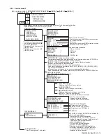
Страница 17: ...menu of a service mode with the button and button Operate choice of a menu with a ENTER button 1 When an ENTER button is pushed in NO EJECT indication it is set by an EJECT prohibition mode When an ENTER button is pushed in EJECT OK indication it is set by a normal mode 2 Forced EJECT movement A screen becomes normal indication after an ENTER button was pushed STANDBY ON ATTENUATOR button 1 3 2 4 ...

Страница 18: ...or three seconds INITIALIZE NOW INITIALIZE INITIALIZE OK INITIALIZE Initialization of a user area of each EEPROM Main micron EEPROM initialization a user entry domain a user entry domain speaker setting subarea of J version data to pre set Panel micron EEPROM initialization picture adjustment data DVD unit EEPROM initialization except a permanent domain After clear completion a screen returns to n...

Страница 19: ...o following indication after clear completion BT VERSION SW BT CORE HW BT MODULE SW BT MODULE ADR Bluetooth version indication Software version of BT core Hardware version of BT Module Software version of BT Module BT Address INITIALIZE ALL Each EEPROM is initialized by a factory shipment state Main micon EEPROM initialization user entry domain error history speaker setting subarea of J version da...

Страница 20: ...pointed position of DVD Position measured with VT 501 jitter value MONITOR Monitor terminal setting DVD 1 PLAY DVD 1 stopped start After start jitter is measured by an inner position Not displayed STOP Disc stopped LD OFF Not displayed EJECT EJECT Not displayed LOAD LOADING Not displayed MONITOR S MODE R W CHROMA DATA CLEAR See Monitor adjustment for details CHROMA DATA read write of NTSC PAL sign...

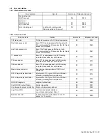
Страница 21: ...ss passes in a DVD running mode for 30 seconds it is not finished 80 0069 T12 access error Even if T12 access passes in a DVD running mode for 30 seconds it is not finished 80 0070 T24 access error Even if T24 access passes in a DVD running mode for 30 seconds it is not finished 80 0071 Read in area read error Read in area read operation of DVD is not completed 84 0072 DVD L1 layer adjustment erro...

Страница 22: ...0 degrees ANGLE 3 error 1 Time out error by ANGLE 3 position cannot detect at moving to open position 2 Missing to ANGLE 2 and detected ANGLE 3 position at moving to open position 3 Time out error by ANGLE 3 cannot detect at moving close position 0E0031 0E0032 0E0033 Moving to 30 degrees ANGLE 4 error 1 Time out error by ANGLE 4 position cannot detect at moving to open position 2 Missing to ANGLE ...

Страница 23: ...n the main unit and insert a test disc VT 501 And play the test disc and pause it Only an item number and value are shows a screen when the choose Monitor S Mode but can operate it by pushing the following area Indication Explanation Operation contents of 1 cycle In mecha error In disc error RUNNING1 MECHA Door mecha running 1 Panel close Panel open RUNNING2 MECHA Door mecha running 2 Panel close ...

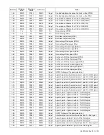
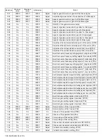
Страница 24: ... revision core ring PAL 022 00000 00006 00032 Adjust Adjustment of the horizontal brightness outline revision gain NTSC 023 00000 00006 00005 Adjust Adjustment of the horizontal brightness outline revision gain PAL 024 00000 00031 00000 Adjust Tap change of the horizontal brightness outline revision NTSC 025 00000 00031 00000 Adjust Tap change of the horizontal brightness outline revision PAL 026 ...

Страница 25: ...255 00005 Adjust Appoint a position of gamma revision 1 point 1 for RGB signal 071 00000 00255 00020 Adjust Appoint a position of gamma revision 1 point 2 for RGB signal 072 00000 00255 00035 Adjust Appoint a position of gamma revision 1 point 3 for RGB signal 073 00000 00255 00048 Adjust Appoint a position of gamma revision 1 point 4 for RGB signal 074 00000 00255 00057 Adjust Appoint a position ...

Страница 26: ... 1 Low lank NTSC 112 Fix Fix 00000 Fix Burst lock center frequency setting register 1 High lank PAL 113 Fix Fix 00000 Fix Burst lock center frequency setting register 1 Low lank PAL 114 Fix Fix 17919 Fix Burst lock phase adjustment upper limit setting register High lank NTSC 115 Fix Fix 65535 Fix Burst lock phase adjustment upper limit setting register Low lank NTSC 116 Fix Fix 17919 Fix Burst loc...

Страница 27: ...ical synchronization signal NTSC 154 00000 00063 00015 Adjust Noise filter band setting of holizontal synchronization signal and vertical synchronization signal PAL 155 Fix Fix 14976 Fix Horizontal phase comparison gain setting NTSC 156 Fix Fix 14976 Fix Horizontal phase comparison gain setting PAL 157 Fix Fix 00055 Fix Horizontal loop filter setting 1 158 Fix Fix 00003 Fix Horizontal loop filter ...

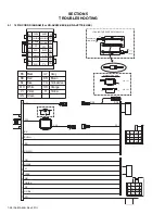
Страница 28: ...BL WH BR OR WH LOCKING THE WIRE WITH INSULOK YL2 YL3 300501 2 CONNECTOR 16PIN MOLEX SET BATT YL2 YL3 YL2 YL3 DIMENSION CASE VIEW TOP VIEW SIDE 1 3 5 7 2 4 6 8 VI GY WH GN VI BK GY BK WH BK GN BK RD1 YL2 BK BL WH BR GN BK VI VI BK WH BK GN GY BK YL 1 WH OR WH RD3 RD2 YG GY BK RD BL WH VI Black Red Blue White Violet GN BR Brown GY Gray YL Yellow Green YG YellowGreen OR Orange YL3 2 16 1 8 13 6 5 7 1...

Страница 29: ... Red Blue White Violet GN BR Brown GY Gray YL Yellow Green YG YellowGreen OR Orange 8 7 6 5 16 15 14 13 4 3 2 1 12 11 10 9 BK RD WH GN VI GY BL WH GN BK VI BK GY BK YL NC WH BK BR YG OR WH BK YL1 RD WH BK GN VI VI BK WH GY BK GY BL WH OR WH YG BR GN BK YL2 2 16 1 11 8 9 6 5 13 10 15 3 12 14 7 ...

Страница 30: ... CUT CONNECTOR 16PIN MOLEX SET BATT 8 7 6 5 16 15 14 13 4 3 2 1 12 11 10 9 BK RD WH GN VI GY BL WH GN BK VI BK GY BK YL BL WH BK BR YG OR WH BK RD BL WH VI Black Red Blue White Violet GN BR Brown GY Gray YL Yellow Green YG YellowGreen OR Orange BK YL1 RD WH BK GN VI VI BK WH BR GY BK GY BL WH OR WH YG BL GN BK YL2 2 16 1 11 8 9 6 5 4 13 10 15 3 12 14 7 ...

Страница 31: ......
Страница 32: ... No MA454 Rev 001 VSE Printed in Japan Victor Company of Japan Limited Mobile Entertainment Division 10 1 1chome Ohwatari machi Maebashi city 371 8543 Japan ...

Отзывы: