(No. 70251) 5
JX-S555(J)
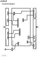
Note : For the positions of the connectors, see the connection
diagram (page 6).
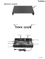
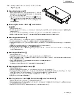
Removing the top cover
1
1
1
1
1
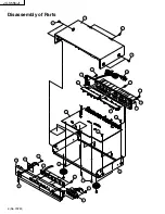
1. Remove the two screws
3
retaining the top cover
1
from the
rear panel
2
, then remove the four screws
4
retaining the
top cover from the side panels.
2. Slightly open out the bottoms of the side skirts
I
of the top
cover
1
as shown in the figure, then pull the top cover straight
upward
II
. Do not remove the top cover by pulling it up in an
oblique direction.
Removing the Audio 1 Board
5
5
5
5
5
and Audio 2
Board
6
6
6
6
6
1. Remove the top cover
1
.
2. From the rear panel
2
, remove the six screws
7
retaining the Audio 1 board
5
and the six screws
7
retaining the
Audio 2 board
6
.
3. Gently remove the Audio 1 board
5
and then unplug the connectors CN809 and CN810 from it.
4. Gently remove the Audio 2 board
6
and then unplug the connectors CN807 and CN808 from it.
Removing the Main Board
B
B
B
B
B
1. Remove the top cover
1
, then the Audio 1 board
5
and finally the Audio 2 board
6
.
2. From the rear panel
2
, remove the nineteen screws
C
retaining the Main board
B
.
3. Unplug the connectors CN1, CN3, CN804 and CN811 (and the wire from the Front Panel Assembly
D
)on the Main
board
B
.
4. Unplug the connector CN901 (in the power supply circuit) on the Main board
B
.
5. Remove the two clamping screws
E
on the Main board
B
.
6. Disengage the three claws of the locking card spacer
F
on the Main board
B
, then remove the Main board by lifting
it in an oblique direction.
Removing the Rear Panel
2
2
2
2
2
1. Remove the top cover
1
.
2. Unplug the connector CN901 (in the power supply circuit) on the Main board
B
.
3. Remove the twelve screws
7
retaining the Audio 1 board
5
and the Audio 2 board
6
, then remove the nineteen screws
C
retaining the Main board
B
.
4. Remove the three screws
H
retaining the bottom chassis
G
and the rear panel
2
.
5. Gently remove the rear panel
2
.
(Take care of the AC power cord
I
connected to the rear panel
2
.)
Removing the Front Panel Assembly
D
D
D
D
D
1. Remove the top cover
1
.
2. Remove the three retaining screws
J
from the bottom of the Front Panel Assembly
D
.
3. Disengage the fittings between the side panels of the Front Panel Assembly
D
with the bottom chassis
G
, then
gently pull out the Front Panel Assembly
D
from the bottom chassis
G
toward the front.
4. Unplug the connectors CN1, CN3, CN804 and CN811 from the Main board
B
.
5. Remove the Front Panel Assembly
D
.
Removing the Front 1 Board
K
K
K
K
K
, Front 2 Board
L
L
L
L
L
and Jack Board
8
8
8
8
8
1. Remove the top cover
1
and the Front Panel Assembly
D
.
2. Remove the two screws
M
retaining the Front 1 board
K
, five screws
M
retaining the Front 2 board
L
and the two screws
9
retaining the Jack board
8
.
3. Remove the Front 1 board
K
, the Front 2 board
L
and the Jack board
8
.
II
I
I
Содержание JX-S555
Страница 18: ...JX S555 J 18 No 70251 IC101 CXA2079Q IC102 108 TC74HC4066AP TOSHIBA IC801 807 NJM4580D JRC ...
Страница 33: ...JX S555 J 12 No 70251 Packing Taping Front marking Main unit 3 5 14 11 10 9 8 12 6 4 3 7 2 1 7 ...
Страница 35: ...JX S555 J 14 No 70251 MEMO ...
Страница 44: ... No 70251SCH 9 JX S555 J Circuit Boards MAIN BOARD J22026 001 ...

