JX-S555(J)
16 (No. 70251)
Symptom
Check Results and Failures
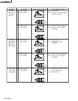
16. Component
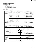
video signal is
not output.
(Y) Q401: Emitter
(Pb) Q402: Emitter
(Pr) Q403: Emitter
NO
YES
Check IC401, IC402 and their
surroundings.
Check 6 dB amp (Q404 to Q409,
Q413 to Q415), output buffer and
their surroundings.
O
(Y)
(Cb)
(Cr)
1.0 Vp-p
0.7 Vp-p
0.7 Vp-p
–
10 dBV
(0.32 Vrms)
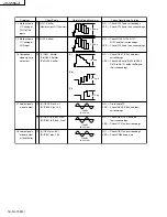
17. Audio signals
are not output.
P
(L) IC806: Pins 6 & 7
(R) IC806: Pins 1 & 2
NO
YES
Go to check
Q
.
Check IC808, IC809 and their
surroundings.
–
10 dBV
(0.32 Vrms)
Q
(L) IC801 to IC805: Pins 7
(R) IC801 to IC805: Pins 1
NO
YES
Check IC801 to IC805 and
their surroundings.
Check IC101 and surroundings.
–
10 dBV
(0.32 Vrms)
18. Audio signals
are not output
at the Monitor.
R
(L) IC807 pins 6 & 7
(R) IC807 pins 1 & 2
NO
YES
Check IC807 and surroundings.
Check CN806 and wire.
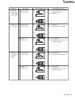
14. Malfunction in
Y/C mixing of
CH1 to CH4
inputs.
Q107: Emitter
(Monitor output: Q115 emitter)
NO
YES
Check IC101 and surroundings.
Check IC103 and their surroundings.
M
2.0 Vp-p
15. Malfunction in
Y/C mixing of
CH5 input.
Q122: Emitter
NO
YES
Check Q105, Q106, Q121,
Q122 and their surroundings.
Check IC103 and their surroundings.
N
2.0 Vp-p
Check Points
Normal Voltage/Waveform
Содержание JX-S555
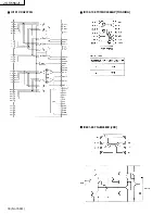
Страница 18: ...JX S555 J 18 No 70251 IC101 CXA2079Q IC102 108 TC74HC4066AP TOSHIBA IC801 807 NJM4580D JRC ...
Страница 33: ...JX S555 J 12 No 70251 Packing Taping Front marking Main unit 3 5 14 11 10 9 8 12 6 4 3 7 2 1 7 ...
Страница 35: ...JX S555 J 14 No 70251 MEMO ...
Страница 44: ... No 70251SCH 9 JX S555 J Circuit Boards MAIN BOARD J22026 001 ...

